3 Mounting Dimension Diagrams
- 42 -
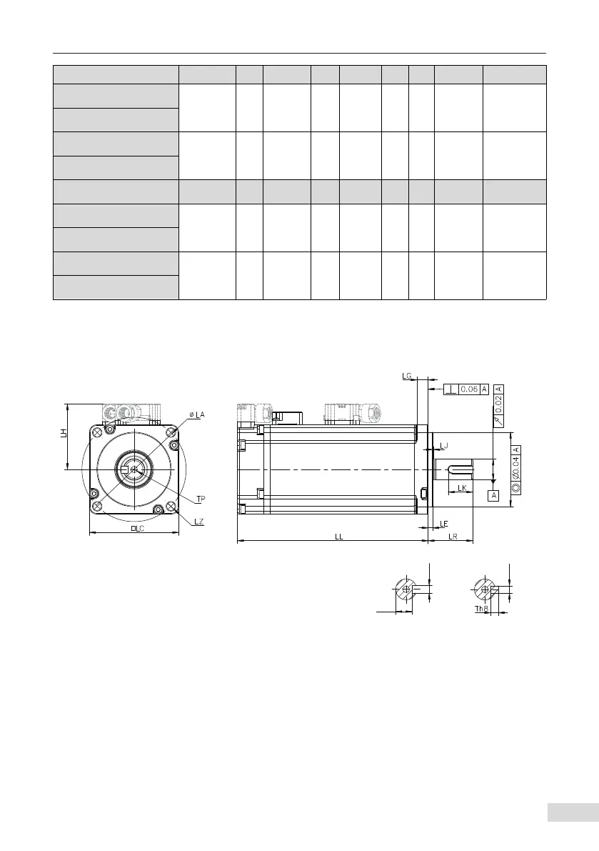
Motor Model LL LC LR LA LZ LH LG LE LJ
MS1H1-05B30CB-A3**Z
65(96) 40 25±0.5 46 2-φ4.5 34 5 2.5±0.5 0.5±0.35
MS1H1-05B30CB-U3**Z
MS1H1-10B30CB-A3**Z
77.5(109) 40 25±0.5 46 2-φ4.5 34 5 2.5±0.5 0.5±0.35
MS1H1-10B30CB-U3**Z
Motor Model S LB TP LK KH KW W T Weigh(kg)
MS1H1-05B30CB-A3**Z
8 30 M3×6 15.5 6.2
0
-0.1
3 3 3 0.39(0.50)
MS1H1-05B30CB-U3**Z
MS1H1-10B30CB-A330Z
8 30 M3×6 15.5 6.2
0
-0.1
3 3 3 0.45(0.64)
MS1H1-10B30CB-U3**Z
3.2 Flange Frame Size: 60
■
Terminal-type motor
keyed shaft end
shaft end diagram
øS h6
0
-0.011
øLB h7
0
-0.025
KW N9
KH
Wh8
 Loading...