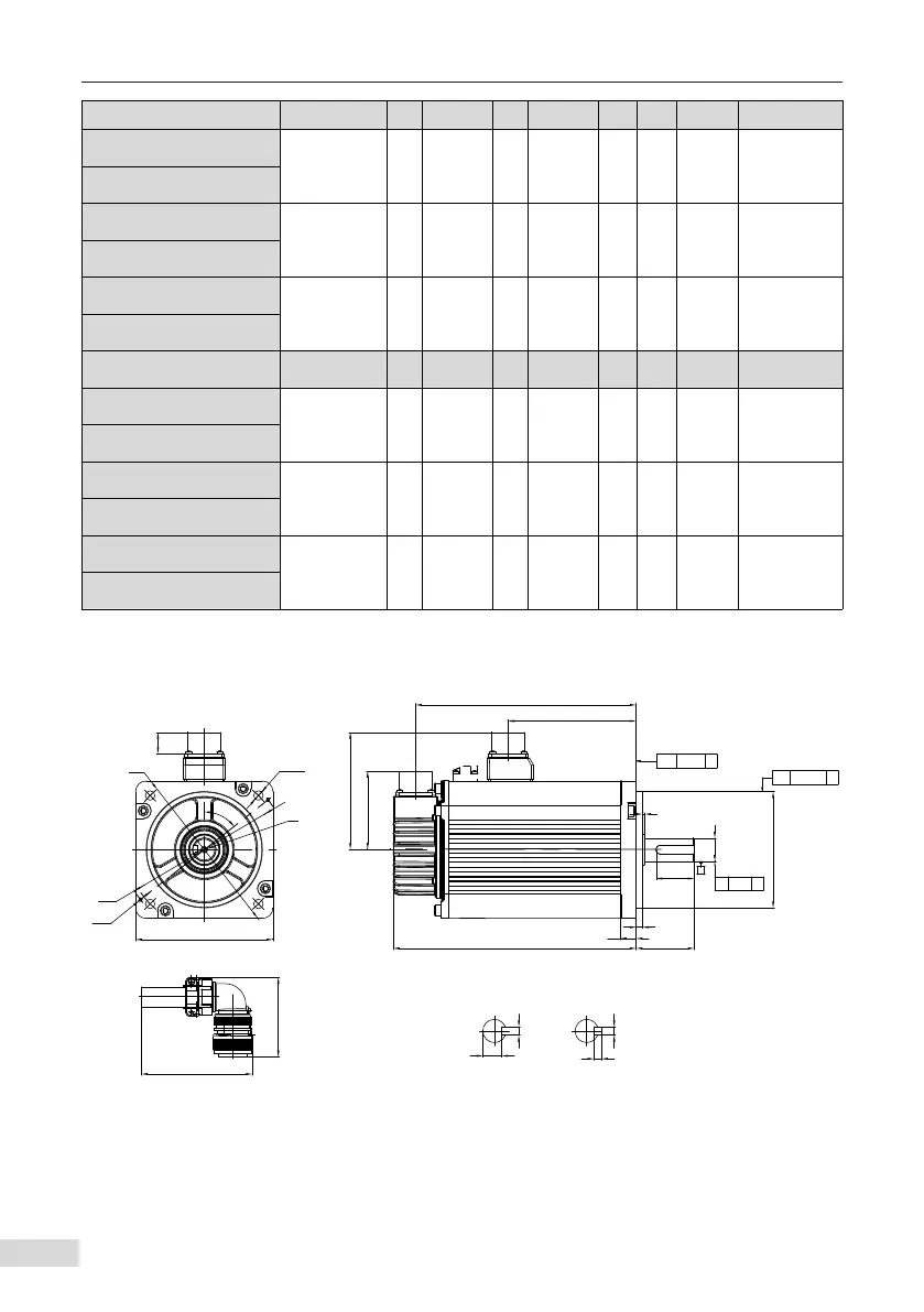
3 Mounting Dimension Diagrams
- 45 -
Motor Model LL LC LR LA LZ LH LG LE LJ
MS1H1-55B30CB-A3**Z
96.2(107) 80 35±0.5 90 4-φ7 54 7.7 3±0.5 0.5±0.35
MS1H1-75B30CB-U3**Z
MS1H1-75B30CB-A3**Z
140(118.2) 80 35±0.5 90 4-φ7 54 7.7 3±0.5 0.5±0.35
MS1H1-10C30CB-U3**Z
MS1H4-75B30CB-A3**Z
117.5(147.5) 80 35±0.5 90 4-φ7 54 7.7 3±0.5 0.5±0.35
MS1H4-75B30CB-U3**Z
Motor Model S LB TP LK KH KW W T Weight(kg)
MS1H1-55B30CB-A3**Z
19 70 M6×20 25 15.5
0
-0.1
6 6 6 1.85(2.18)
MS1H1-75B30CB-U3**Z
MS1H1-75B30CB-A3**Z
19 70 M6×20 25 15.5
0
-0.1
6 6 6 2.82(2.55)
MS1H1-10C30CB-U3**Z
MS1H4-75B30CB-A331Z
19 70 M6×20 25 15.5
0
-0.1
6 6 6 2.40(3.04)
MS1H4-75B30CB-A334Z
3.4 Flange Frame Size: 100
■
Dimension drawing for MS1H2 series motors in frame size 100
ØLA
LZ EQS
□LC
KA2
KA1
LL
LG
LE
LR
LK
ØSh6
0
-0.013
ØLBh7
0
-0.035
KW N9
KH
W h8
T h11
KB1
LJ
18.5
100
80
⏊ 0.10 A
A↗ 0.03
◎ Ø0.06 A
Ø118
TP
52°
shaft end diagram keyed shaft end
AA
仅抱闸电机
 Loading...