24
Installation
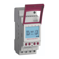
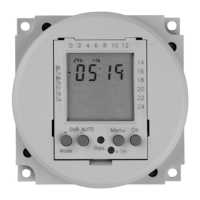
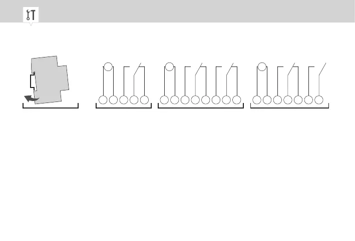
Fig. 5: Installation on a DIN rail and circuit diagrams
A Installation on a DIN rail
B 110 – 230V 1-channel DIN-rail timer
C 110 – 230V 2-channel DIN-rail timer
D 12/24V DIN-rail timer
1. Place the DIN-rail timer on the DIN rail (Fig.5/A) from above and press it back until it locks into
place.
2. Install the DIN-rail timer in accordance with the circuit diagram (Fig.5/B), (Fig.5/C) or (Fig.5/D)
(use wires with a cross-section between 1mm² and 2.5mm²).
L N
M
~
1 2 3
M
~
1 2 3 5 6
~-
L N
M
~
1 2 3 5 6
7
BA C D
 Loading...