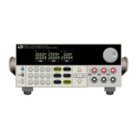
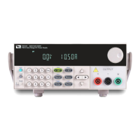
Do you have a question about the ITech CalPower IT6302 and is the answer not in the manual?
Dimensions | 215mm x 150mm x 350mm |
---|---|
Weight | 7.5kg |
Interface | USB, RS232 |
Operating Temperature | 0°C to 40°C |
Output Current | 0-3A (CH1, CH2), 0-15A (CH3) |
Current Range (CH1) | 0 ~ 3A |
Current Range (CH2) | 0 ~ 3A |
Resolution (Current) | 1mA |
Ripple & Noise (Current) | ≤3mArms |
Explains CAUTION, WARNING, and NOTE signs, their meanings, and safety precautions.
Includes copyright, warranty disclaimers, trademarks, and license information.
Confirms the IT6302 power supply meets published specifications at shipment.
Details ITECH's one-year warranty against defects and outlines specific limitations.
Details critical safety measures for instrument operation, including warnings and cautions.
Specifies the required environmental conditions for proper instrument operation.
Explains CE, WEEE, and EFUP markings, indicating product compliance and disposal information.
Provides an introduction to remote configuration and SCPI commands.
Defines SCPI as a communication method for instruments using ASCII and a hierarchical tree system.
Explains SCPI commands as common (e.g., *RST) or subsystem (e.g., CURR:LEV).
Details SCPI command syntax, including parameters, optional elements, and separators.
Describes SCPI data types: numerical, discrete, boolean, and ASCII string parameters.
Explains connecting the instrument via RS232/USB and communication settings.
Describes the four status register groups: byte, standard event, query, and operation registers.
Commands for error, version, remote/local control, beeper, and lock functions.
Manages query event registers, enabling/disabling and querying status.
Manages operation event registers, enabling/disabling and querying status for channels.
Includes immediate trigger generation and setting trigger delay times.
Controls output switches, series/parallel channel states, and clears protection.
Commands to set, increase, decrease, and trigger current levels for channels.
Commands to set, increase, decrease, trigger voltage levels, and set upper limits.
Applies combined voltage and current settings to a specific channel.
Reads output current, voltage, and power values from the instrument's channels.
Selects channels, specifies trigger channels, and combines channels in series/parallel.
Manages calibration security state, defines voltage/current calibration points, and retrieves values.
Saves, initializes, and sets calibration information strings.
Clears registers, enables/queries standard event status, and identifies the instrument.
Manages OPC bit, PSC command, reset, and state byte enable register.
Reads status byte register data and generates trigger signals.
Saves/recalls setups, queries self-test results, and waits for operations.