Function and Features
Copyright © Itech Electronic Co., Ltd. 30
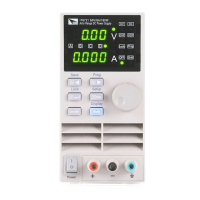
Vo+, Vo- : output terminals, the same with front panel output terminals;
Vs+, Vs- : remote sense pins.
NC, NC : No conjunction.
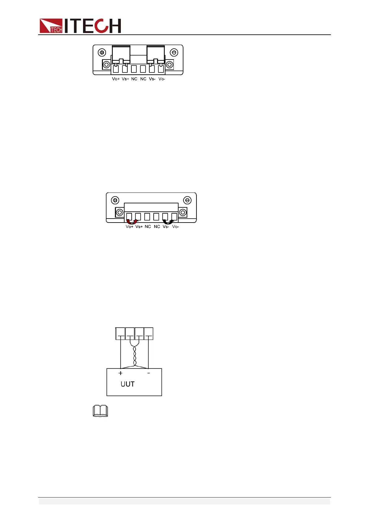
Use local sense:
Local sense doesn’t compensate the voltage drop on the connection wire, the
operation is:
1. Use the short clips on the back panel of the instrument, or install wire
between Vo+ and Vs+ 、Vo- and Vs-.
2. Connect the positive and negative terminals of the front panel to the device
under test.
Use remote sense:
Disconnect the wires between “+,-”pins if you want to use remote sense
function. Then lead a wire from S+,S- pins and connect to the under test
objects.
1. Disconnect the wires/short clips between Vo+ and Vs+、 Vo- and Vs-.
2. Connect wires from Vs+ 、Vs- to the device under test.
3. Connect wires from Vo+ 、Vo- to the device under test.
NOTE
In order to ensure the stability of the system, using armored twisted pair cable between
the remote sense terminal of IT6700 and load.
Please note that the positive and negative polarity when wiring, otherwise it will damage
the instrument!

 Loading...