EasyManua.ls Logo

ITech IT6700 Series User Manual

ITech IT6700 Series
57 pages
To Next Page IconTo Next Page
To Previous Page IconTo Previous Page
Page #56 background image
Appendix
Copyright © Itech Electronic Co., Ltd. 48
Appendix
Specifications of Red and Black Test Lines
ITECH provides you with optional red and black test lines, which individual
sales and you can select for test. For specifications of ITECH test lines and
maximum current values, refer to the table below.
Model
Specification
Cross section
Length
IT-E301/10A
10A
-
1m
IT-E301/30A
30A
6mm
2
1.2m
IT-E301/30A
30A
6mm
2
2m
IT-E301/60A
60A
20mm
2
1.5m
IT-E301/120A
120A
50mm
2
2m
IT-E301/240A
240A
70mm
2
1m
IT-E301/240A
240A
70mm
2
2m
IT-E301/360A
360A
95mm
2
2m
For maximum current of AWG copper wire, refer to table blow.
AWG
10
12
14
16
18
20
22
24
26
28
The
Maximum
current
value( A)
40
25
20
13
10
7
5
3.5
2.5
1.7
Note: AWG ( American Wire Gage), it means X wire ( marked on the wire). The
table above lists current capacity of single wire at working temperature of 30°C.
For reference only.
Question and Answer IconNeed help?

Do you have a question about the ITech IT6700 Series and is the answer not in the manual?

ITech IT6700 Series Specifications

General IconGeneral
BrandITech
ModelIT6700 Series
CategoryPower Supply
LanguageEnglish

Summary

Statement and Safety Notices

Legal Statements

Covers guarantee, technology license, and U.S. government permissions.

Safety Indicator Definitions

Explains CAUTION, WARNING, and NOTE signs for safe operation.

Certification and Quality Assurance

Warranty Service

Details service terms, limitations, and procedures.

Limitation of Warranty

Lists conditions under which warranty service does not apply.

Safety Signs

Explains common electrical safety symbols.

Safety Precautions

Electrical Safety Warnings

Emphasizes grounding, proper wiring, and avoiding damaged equipment.

Shock Hazard Warnings

Highlights risks of lethal voltages and necessary precautions.

Operational Cautions and Conditions

General Cautions

Important warnings about product use, cleaning, and ventilation.

Environmental Requirements

Specifies conditions for optimal and safe operation.

Regulation Tags

Explains compliance symbols like CE, UKCA, and WEEE.

WEEE Directive Compliance

Compliance Information

EMC Standards

Lists electromagnetic compatibility standards and references.

Safety Standards

Lists the relevant safety standard IEC 61010-1.

Chapter I: Acceptance and Installation

Confirm Package Contents

Verifying all items are received in good condition.

Installation Position

Installation Procedures

Rack Mounting

Instructions for installing the unit in a 19-inch rack.

Power Cord Connection

Steps for connecting the AC power cord.

AC Power Input and Connections

Input Voltage Levels

Information on different input voltage requirements for models.

Power Cord Types

Details available power cord categories.

Connecting AC Input

Step-by-step guide for power connection.

Connecting the DUT

Pre-connection Checks

Safety and preparation steps before connecting the DUT.

Binding Post and DUT Connection

Binding Post Usage

Explanation of binding post functions and current ratings.

DUT Connection Steps

Detailed procedure for connecting the device.

Chapter II: Quick Start

Brief Introduction to IT6700 Series

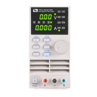
Overview of product features and capabilities.

Front Panel Overview

Key Functions and Introduction

Front Panel Key Descriptions

Explains the purpose of each key on the front panel.

VFD and Rear Panel Introduction

VFD Indicator Meanings

Explains the symbols and status displayed on the VFD screen.

Rear Panel Layout

Describes the connectors and components on the rear panel.

Power-on Self-Test and Error Handling

Power-on Self-Test Procedure

Steps for initiating and verifying the self-test.

Error Information and Exceptions

References for common errors and troubleshooting steps.

Chapter III: Function and Features

Local/Remote Operation Modes

How to switch between front panel and PC control.

Voltage and Current Setup

Methods for setting output voltage and current.

Output Control and Adjustment

Output On/Off and Value Switching

Controlling output and displaying values.

Voltage/Current/Power Adjustment

Methods for adjusting output parameters.

Save/Recall Parameters

Storing and retrieving frequently used settings.

Menu Operations and Triggering

Trigger Operation

Using trigger sources for list file execution.

Menu Navigation

How to access and use the instrument's menu system.

Chapter IV: Technical Specification

Main Technical Parameters

Detailed specifications for various models.

Protective Functions

Over Voltage Protection (OVP)

Details the OVP function and its settings.

Over Current Protection (OCP)

Explains the OCP feature.

Additional Protection and Functions

Over Temperature Protection (OTP)

Describes the OTP function.

Key Lock Function

How to lock/unlock panel buttons.

Remote Sense Function

Compensating for voltage drop during testing.

Chapter V: Remote Operation Mode

RS232 Interface Setup

Connecting and configuring the RS232 port.

Communication Interfaces and Troubleshooting

RS232 Troubleshooting

Solutions for RS232 connection issues.

USB Interface Usage

Connecting and programming via USB.

Advanced Communication Interfaces

RS485 Interface Configuration

Setting up RS485 for multi-unit control.

GPIB Interface Connection

Connecting and configuring the GPIB interface.

Appendix

Test Line Specifications

Details for optional test leads.

Contact Information

Related product manuals