Basic Operations
Copyright © ITECH Electronic Co., Ltd. 34
NOTE
Only IT8615, IT8615L and IT8620 series are with the function.
⚫ IT8615/IT8615L electronic load: Up to nine units of the same voltage and
current rating can be connected in parallel.
⚫ IT8620 series (IT8624/IT8625/IT8626/IT8627/IT8628): Up to three units of
the same voltage and current rating can be connected in parallel.
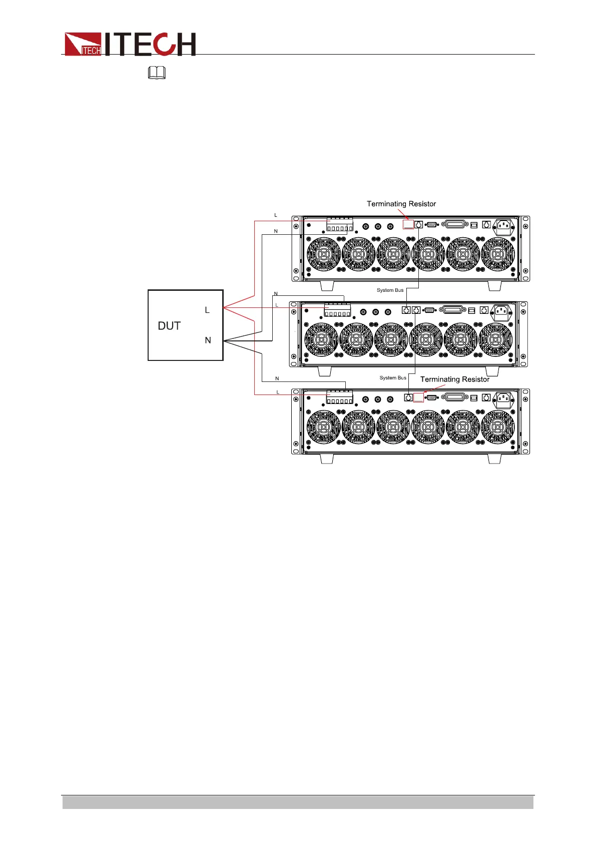
Take the example of IT8615 electronic load, the schematic diagram of parallel
connection is as follows. When you connect system bus, the Terminating
Resistor is a must for the first load unit and the last load unit.
Configure the internal relationship of instruments after connecting the system
bus. In the parallel mode, the master and slaves are determined by the
instrument setting. If the instrument is set to Master, the present AC load is the
master unit, and if the instruments are set to Slave, the AC loads are slaves.
The user should set the total number of slave or unit in master to determine the
electronic load power in the present mode.
When the AC load is set in the parallel operation mode, slaves should be set
with priority to correctly set the total number of parallel units during master unit
setting.
The configuration interface of IT8620 series and IT8615/IT8615L are not the
same. The specific setting steps are as follows.
⚫ Take the parallel connection of two IT8615 electronic loads as an example.
Select one electronic load as the slave.
1. Press [Menu] to enter the system menu setting interface.
2. Select [PARALLEL SETUP] to enter the parallel setting interface.
3. Press the Up and Down key to select the “Operating Mode” > “Parallel”.
4. Set “Master/Slave” as Slave, as shown below:
ООО "Техэнком" Контрольно-измерительные приборы и оборудование www.tehencom.com
 Loading...