Maintenance
AirModule 6 720 813 268(2014/10)
60
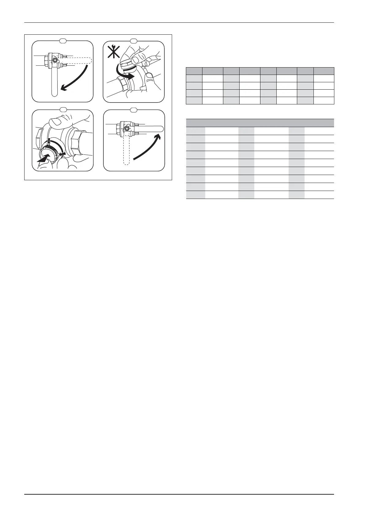
Fig. 51 Filter version without circlip
▶ Screw back the hood (by hand).
▶ Open the valve (4).
Temperature sensor measured values
Heat pump module
Temperature sensor in, or connected to, the heat pump module (T0, T1,
TW1, TC0, TC1) contains measured values according to fig. 43 and 44.
1.
2.
2.
1.
1
2
3
4
6 720 805 915-01.1I
°C °C °C °C
20 12488 40 5331 60 2490 80 1256
25 10001 45 4372 65 2084 85 1070
30 8060 50 3605 70 1753 90 915
35 6536 55 2989 75 1480 – –
Table 43 Flow and DHW temperature sensor T0, TW1, TC0, TC1
°C
T...
°C
T...
°C
T...
–40 154300 5 11900 50 1696
–35 111700 10 9330 55 1405
–30 81700 15 7370 60 1170
–25 60400 20 5870 65 980
–20 45100 25 4700 70 824
–15 33950 30 3790 75 696
–10 25800 35 3070 80 590
–5 19770 40 2510 85 503
0 15280 45 2055 90 430
Table 44 Outside temperature sensor T1
 Loading...


