2-4 4271491-Second Edition
SPECIFICATIONS AND GENERAL INFORMATION
2
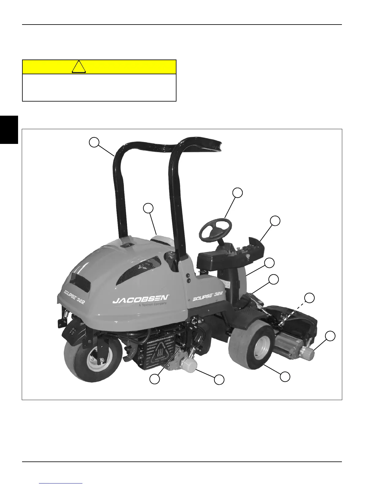
Component Location
See Figures 2-5 through 2-7.
All Models
Figure 2-5: Component Location—Right Side
Become familiar with operator controls, machine
components, and correct operating procedures
before beginning repair procedures.
1OPS 5Steering Tower 9 Front Wheel (2)
2 Seat 6 Traction Pedal 10 Center Cutting Unit
3 Steering Wheel 7 Right Reel Leveling Rod 11 Center Reel Leveling Rod
4Armrest Assembly 8 Right Cutting Unit

 Loading...