3-20 4271491-Second Edition
GENSET AND BATTERY PACK
3
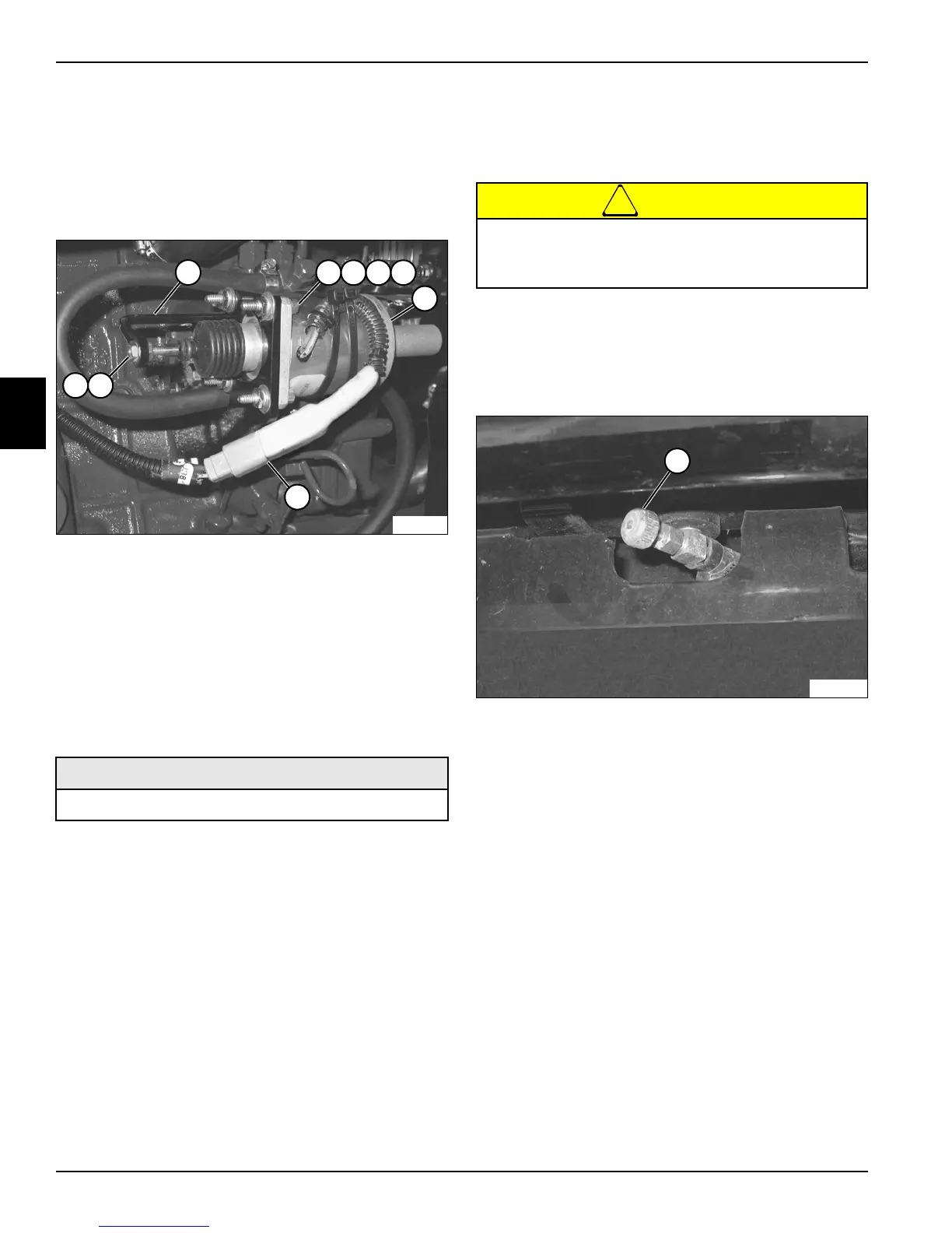
Throttle Actuator (Diesel Models)
Removal and Installation
See Figure 3-25.
1. Park the mower safely. (See “Park Mower Safely” on
page 1-6.)
Figure 3-25
2. Tag and disconnect throttle actuator connector (7).
3. Remove governor linkage arm nut (8) and two
washers (9), and disengage governor linkage arm (1)
from throttle actuator (6).
4. Remove four nuts (2), lock washers (3), flat washers
(4), and screws (5).
5. Remove throttle actuator (6).
Installation Notes
• Install throttle actuator by reversing the order of
re
mo
val.
• Apply Loctite
®
242 (Blue) to two governor linkage
arm nuts (8) prior to assembly.
• Tighten governor linkage arm nuts (32) to 40 lb-in.
(4.5 N·m).
• Adjust throttle actuator linkage. (See “Throttle
Actuator Adjustment (Diesel Models)” on page 3-11.)
Fuel Tank (Diesel Models)
Removal and Installation
See Figures 3-26 through 3-28.
1. Park the mower safely. (See “Park Mower Safely” on
page 1-6.)
2. Allow the engine to cool completely.
3. Raise the hood.
Figure 3-26
4. Close fuel shutoff valve (1). (Turn clockwise until
valve bottoms lightly.)
Required Materials
Loctite
®
242 (Blue)
Diesel fuel is highly flammable. Do not drain fuel
indoors. Heaters can ignite fuel vapors. Use
extreme caution when draining fuel.

 Loading...