20
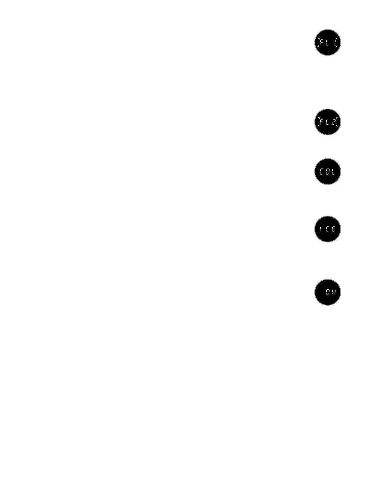
FL1 & FL2 Water Flow Problem (All Models)
• FL1: ow or pressure switch not closed when circulation pump is running. Heater is deacti-
vated. Proper water ow is inhibited or ow/pressure switch may be obstructed, misaligned,
or defective. Refer to troubleshooting steps 1-5 below:
1. Remove lter and allow air to bleed out of cartridge. Check lter for trapped air.
2. Check for proper water level.
3. Check for clogged lter cartridge.
4. Check for sticking or damaged oating skimmer.
5. If problem persists, refer to Section 7.4 (page 21) for ow/pressure switch testing instructions.
• FL2: ow switch or pressure switch closed when pump is not running. Heater is deactivated
and pump may or may not turn on. Flow/pressure switch is defective. Refer to Section 7.4
(page 21) for switch testing instructions.
COL Cool Condition (All Models)
If the water temperature drops 20°F (11°C) below the set temperature, the low speed pump and
heater will activate to raise the water temperature within 15°F (8°C) of the set temperature. No
corrective action is necessary. This condition is common during water changes and/or rst time ll
ups.
ICE Freeze Condition (All Models)
A potential water freeze condition of 55°F (13°C) has been detected. No action is required. The
low speed pump and heater will activate and raise water temperature to approximately 65°F
(18°C), canceling the “ICE” error message. After the error message is canceled, the low speed
pump will turn off (circulation pump models only) and the heater will remain on until the set tem-
perature is reached.
OH Overheat Condition (All Models)
Water temperature is above acceptable limits. DO NOT ENTER HOT TUB WATER! Water tem-
perature has reached 116°F (47°C) and the low speed pump has activated to circulate water
through the heater to cool it down for approximately 6 minutes. Refer to test steps 1-4 below:
1. Verify actual water temperature with an accurate thermometer. If actual water temperature is
less than 110°F (44°C), proceed to steps 2-4.
2. Turn off main breaker to hot tub. Refer to appendix page 56 for expected hi-limit/temperature sensor
resistance/water temperature values.
3. Remove hi-limit sensor connector from circuit board points 22. Verify that the heater is not excessively hot.
Refer to pages 50-53 for your circuit board conguration. Set ohmmeter to 100-200 kΩ range, then
measure resistance across sensor wires (refer to page 56). If resistance tests OK (± 200Ω), check wiring
harness connections. If wiring harness connections test OK, replace circuit board. If sensor resistance is
incorrect, replace hi-limit sensor.
4. Set ohmmeter to 100-200 kΩ range, then measure resistance across temperature sensor wires (refer to
page 56). If resistance tests OK (± 200Ω), replace circuit board. If temperature sensor resistance is
incorrect, replace sensor.
 Loading...