21
“- - -” Watchdog (All Models)
Water temperature has reached 118°F (48°C). DO NOT ENTER HOT TUB WATER! The entire
system is disabled. Refer to test steps 1-4 below:
1. Check hi-limit and temperature sensor resistance values. Both sensors should measure
close in resistance to each other (e.g. one may be defective and way out of range). Refer
to appendix page 56 for expected hi-limit/temperature sensor resistance/water tempera-
ture values. If either sensor is faulty, replace it and recheck system. If problem persists, proceed to steps 2.
2. Plug in new control panel. If problem persists, proceed to step 3. If problem corrects, replace panel.
3. Check voltage at transformer secondary. Refer to Section A29, page 58 for transformer testing instruc-
tions. If voltage is bad, replace transformer. If voltage is good, perform step 4.
4. Check circuit board transformer connections. If connections are loose or oxidized, repair connections and
retest system. If problem persists, replace circuit board.
7.4 Testing Flow/Pressure Switch
Testing The Flow Switch
•All J-LX Models
•All 2011-2013 J300 Models
•All J200 Models (with the Circulation Pump Option)
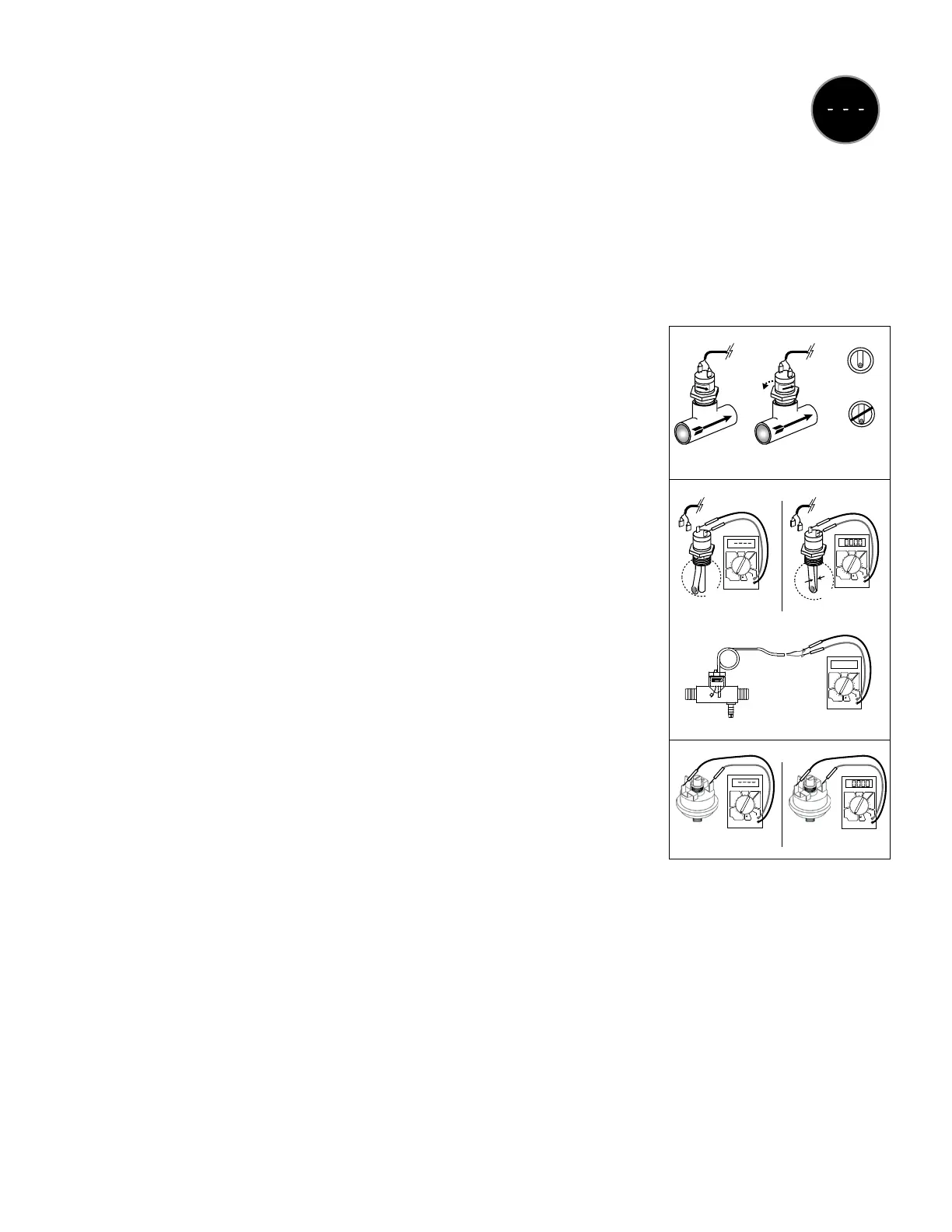
A. Verify ow switch directional arrow is pointing in the direction of ow away
from the heater output. If switch orientation is incorrect, loosen or tighten
switch no more than 1/2 turn, being careful not to bottom out switch in tting.
The switch’s ow arrow must be parallel to tee tting as shown (Fig. 1). Test
system operation. If condition corrects, skip steps B-C.
B. Remove switch from tting making note of the number of turns (revolutions)
it takes to do so. Visually inspect switch for debris interference or damage.
If debris is present, remove debris, then install switch with the same number
of turns as originally installed. Test system. If switch is damaged, replace
switch and retest system. If condition corrects, skip step C.
C. Test switch operation with an ohmmeter (set to 1000-
2000 Ω range) for continuity across switch terminals. Measure resistance
across switch terminals for innite resistance with the magnet arm not
touching the switch body (Fig. 2), and for continuity (0 Ω) with the magnet
arm touching the switch body (Fig. 2). If ow switch tests OK, check switch
wiring harness. If wiring harness tests OK, replace circuit board.
D. Verify that low ow is not preventing the ow switch from closing.
Testing The Pressure Switch
•All J200 Models (without the Circulation Pump)
A. Remove switch. Visually inspect switch for debris blockage. If debris is present, remove debris, install
switch and test system. If condition corrects, skip step B.
B. Disconnect wires from switch terminals. Set ohmmeter to 1000-2000 Ω range. Measure resistance across
switch terminals for innite resistance with pump off (Fig. 3). If continuity (0 Ω) is measured with pump off,
the switch is defective, replace switch. If switch measures innite Ω (no continuity) with pump off, switch
is OK. Turn on main pump and measure across switch terminals for continuity (0 Ω). If continuity (0 Ω) is
measured, switch is OK. Check wiring harness. If wiring harness tests OK, replace circuit board.
If the switch tests ok in the steps above, check the wiring harness connections between switch and circuit
board. Scrape the switch’s contact pin surfaces to remove any oxidation or conformal coating.
FLOW
Incorrect
Orientation
Correct
Orientation
FLOW
Fig. 2
Fig. 1
Fig. 3
Pipe
End View
correct
incorrect
Arrows
not
aligned
Arrows
aligned
Pump on
Pump off
Open
Closed
DCV ACV
DCA
OFF
1000
200
20
2000m
200m
2000k
200k
20k
2000
200
10A
200m
20m
2000µ
200µ
Ω
+
750
200
DCV ACV
DCA
OFF
1000
200
20
2000m
200m
2000k
200k
20k
2000
200
10A
200m
20m
2000µ
200µ
Ω
+
750
200
DCV ACV
DCA
OFF
1000
200
20
2000m
200m
2000k
200k
20k
2000
200
10A
200m
20m
2000µ
200µ
Ω
+
750
200
DCV ACV
DCA
OFF
1000
200
20
2000m
200m
2000k
200k
20k
2000
200
10A
200m
20m
2000µ
200µ
Ω
+
750
200
DCV ACV
DCA
OFF
1000
200
20
2000m
200m
2000k
200k
20k
2000
200
10A
200m
20m
2000µ
200µ
Ω
+
750
200
Infinite Ω
Continuity 0 Ω
Infinite Ω
Continuity 0 Ω
 Loading...