Page 16
4.3 Main Power Center PCB
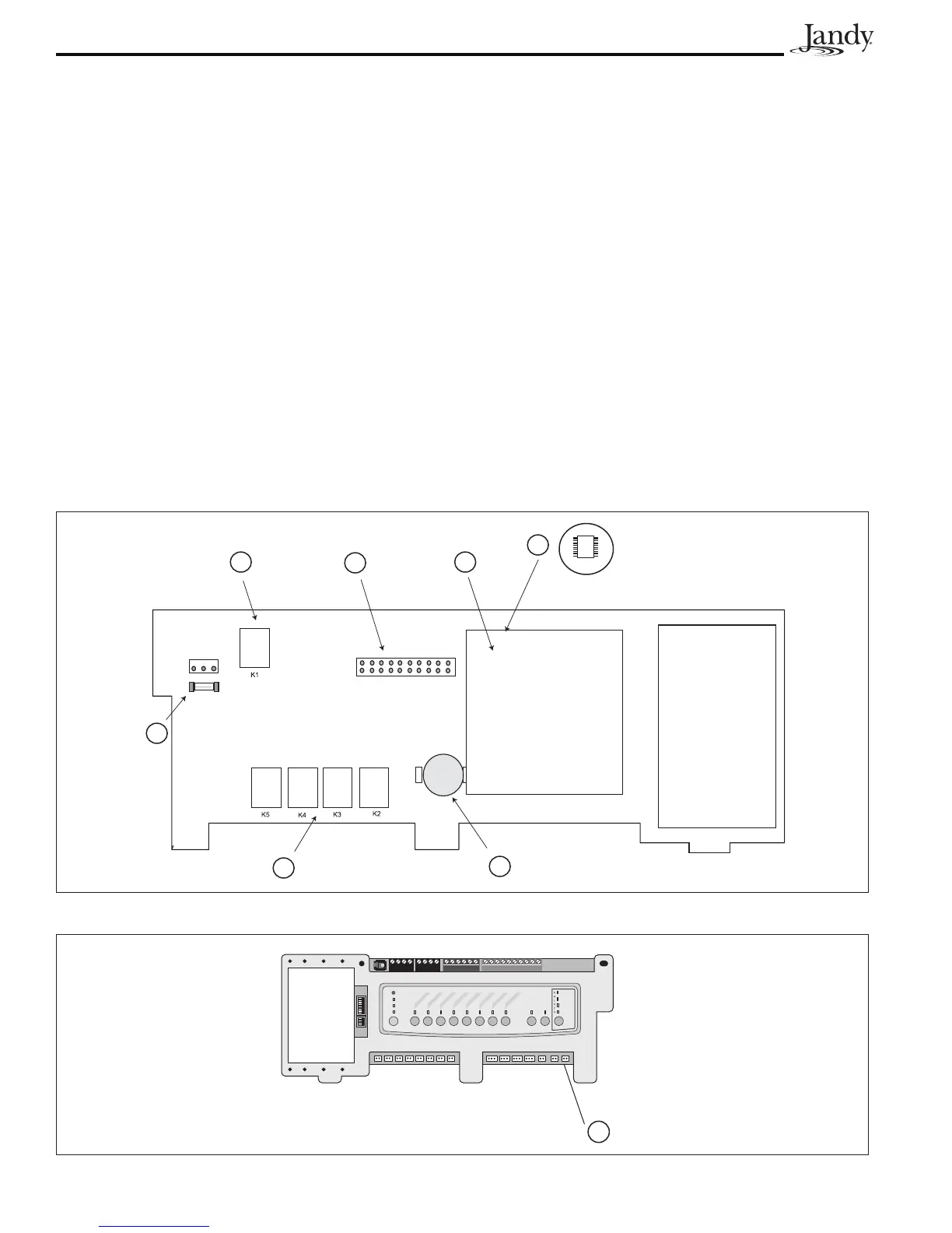
4.3.1 PCB Circuit Layout
1. JVA Relays (K2 - K5)
2. Low Voltage Heater Relay
3. 3.15 amp fuse. Fuse will blow to protect the transformer when there is a short circuit in the JVA(s) or the circuit
board driver chip is damaged.
4. CPU Board
5. U2 Communication Chip. This chip will be damaged if a lightning strike hits the four (4) conductor wires. It will
turn brown when damaged. This chip is mounted on the PCB board and is located underneath the top edge of the
CPU board.
6. Sprinkler Module Connector
7. Battery (3 Volt Lithium)
8. Spare Auxiliary. Operates with pool/spa combo units only. With fi rmware prior to Rev. I this socket is on when
the fi lter pump is on and the system is in pool mode. It turns off when the spa is activated. With Rev. I or newer,
turning on dip switch 6 will reverse the operation of this socket (i.e. on in spa mode and off in pool mode).
Figure 10. Main Power Center PCB, Back View
Figure 11. Main Power Center PCB, Front View
2
6
4
5
1
7
3
S1
S2
654321
10987654321
4321
4321
RESET
SERVICE
TIME OUT
FIL
TER PUM
P
AUX
1
AUX
2
AUX 3
A
UX 4
A
UX 5
A
UX
6
AUX
7
RS6 & RS8 ONLY
RS8 ONLY
HEATER
SOLAR
POOL MODE
SPA MODE
SPA DRAIN
SPA FILL
AUTO
8
 Loading...