EasyManuals Logo
Home>Jandy>Control Systems>AquaLink RS series

Jandy AquaLink RS series User Manual

Jandy AquaLink RS series
48 pages
To Next Page IconTo Next Page
To Previous Page IconTo Previous Page
Page #43 background imageLoading...
Page #43 background image
Page 43
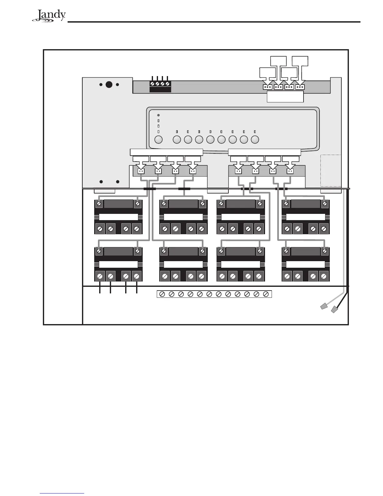
9.3 AquaLink RS Auxiliary Power Center
Aux B 1 R elay
Aux B 4 R elay
Aux B 2 R elay
Line One
Low Vo ltage Raceway (do not run high volt
age wire in this compartment)
Line Two
Load One
Load Two
Aux B 3 R elay
Grounding Bar
Wire Nut to
120 VA C P ower
System Powe r
Aux B 1
JV A
Aux B 3
JV A
Aux B 2
JV A
Aux B 4
JV A
Yellow
Green
Black
Re d
4321
Aux B 1
Aux B 2 Aux B3 Aux B 4
Relay Sockets (24 VDC output)
Aux B 8Aux B 7Aux B 6Aux B 5
Relay Sockets (24 VDC output)
JV A S ockets
(24 VA C output)
To Power Center #1
(or Indoor Control Panel)
Aux B 5 R elay
Aux B 8 R elay
Aux B 6 R elay Aux B 7 R elay

Other manuals for Jandy AquaLink RS series

Questions and Answers:

Question and Answer IconNeed help?

Do you have a question about the Jandy AquaLink RS series and is the answer not in the manual?

Jandy AquaLink RS series Specifications

General IconGeneral
BrandJandy
ModelAquaLink RS series
CategoryControl Systems
LanguageEnglish

Related product manuals