12
MC450e
Printed circuit board L2
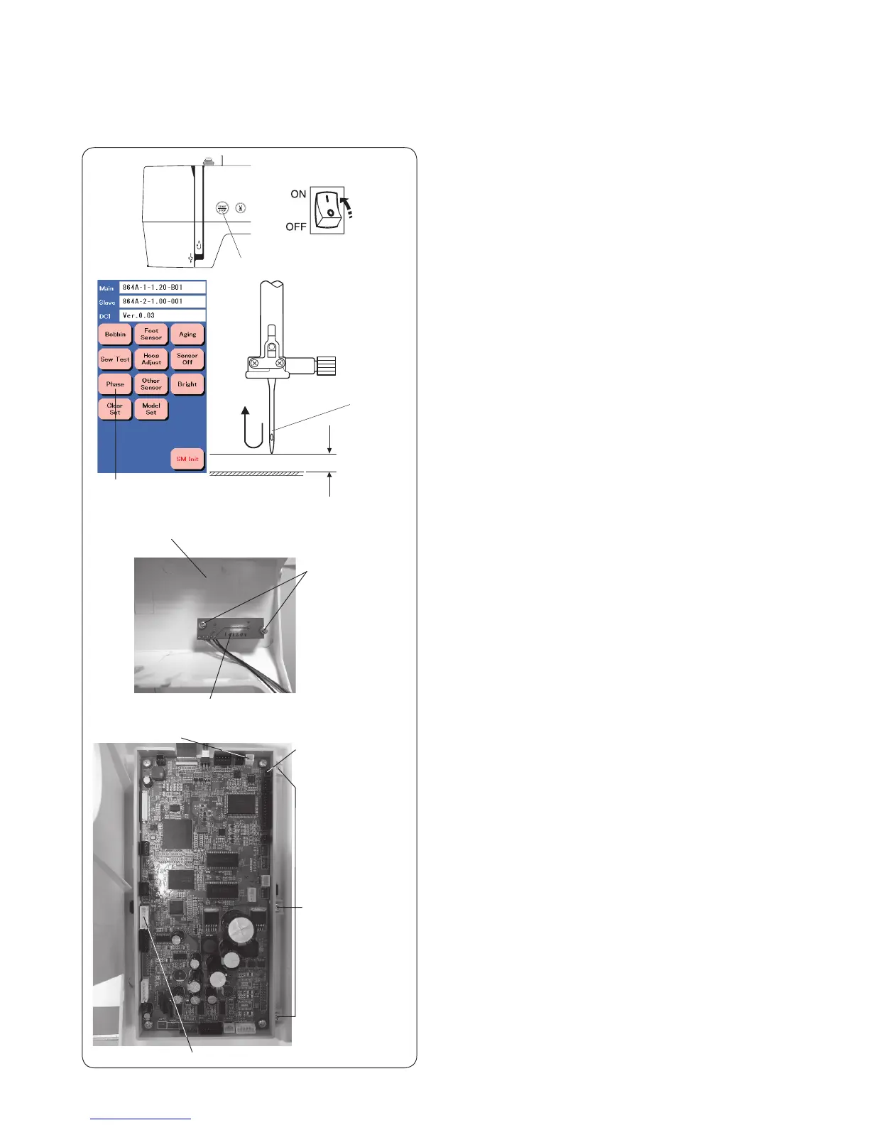
Adjusting the Upper Shaft Shield Position
1. Remove the face cover, bed cover and front cover (refer
to pages 1,3 and 4). Attach the needle plate.
2. Remove the setscrews (A) and printed circuit board F
from the front cover.
The needle height should be at 8.2-9.2 mm above the needle plate surface when the “Bight” phase
changes from “L” to “H”.
Setscrews (B)
Setscrews (A)
Front cover
Printed circuit board F
3. After disconnecting all of the connector, remove the
setscrews (B) to remove the printed circuit board A
from the front cover.
4. Reconnect the connectors to the printed circuit board
A except printed circuit board L2 and L3 connectors.
* The carriage will not return to the home position after
turning the power switch on if the X-motor connector
is disconnected.
(To be continued to the next page.)
X motor connector
Printed circuit
board L3
Phase key
To adjust:
To check:
1. Attach the needle #11.
Turn the power switch on while pressing the Start/
stop button to enter the factory setting mode.
Press “Phase” key.
2. Turn the handwheel toward you slowly until the
needle from its lowest position until “Bight” changes
from “L” to “H”.
3. The needle height should be 8.2 to 9.2 mm above
from the surface of the needle plate. If not, adjust the
upper shield position.
8.2–9.2 mm
#11 Blue needle
Start/stop button
 Loading...