EasyManua.ls Logo

Janome MC400E User Manual

Janome MC400E
35 pages
To Next Page IconTo Next Page
To Previous Page IconTo Previous Page
Page #28 background imageLoading...
Page #28 background image
26
MC450e
Y-sensor Position Adjustment
Setscrew (A)
Y-shield plate
Y-sensor
B
A
Adjustment
1. Remove the face cover, bed cover and front cover (refer
to pages 1, 3 and 4).
2. Remove the printed circuit board F from the front
cover.
3. After disconnecting all of the connector, remove the
printed circuit board A from the front cover.
4. Reconnect the connectors to the printed circuit board
A except printed circuit board L2 and L3 connectors.
5. Remove the carriage cover (refer to page 6).
6. Turn the power switch ON while pressing the start/
stop button.
Press “SM Init” key.
7. The gap between the hoop attaching base and Y-shaft
xing plate should be 7 mm.
Loosen the setscrew (A) and slide the Y-sensor plate
in the direction of A or B to adjust the position of the
Y-sensor plate.
8. Turn the power switch OFF and turn it ON again to
check if the gap is 7 mm.
9. Tighten the setscrew and turn the power switch OFF.
SM Init key
6. 8 -7. 2 m m
Y-shaft
xing plate
Hoop attaching
base
The gap between the hoop attaching base and Y-shaft xing plate should be 7 mm.
Question and Answer IconNeed help?

Do you have a question about the Janome MC400E and is the answer not in the manual?

Janome MC400E Specifications

General IconGeneral
TypeEmbroidery Machine
Embroidery Area7.9" x 7.9" (200mm x 200mm)
Built-in Designs160
Built-in Fonts6
DisplayLCD Touch Screen
ConnectivityUSB
Weight18.5 lbs
Needle ThreaderYes
Maximum Stitch Width7 mm
Maximum Stitch Length5 mm
Built-in MemoryYes
Speed ControlYes
Drop FeedYes
Free ArmNo
Presser FeetEmbroidery Foot

Summary

Replacing External Parts (1) Face Cover and Thread Cutter Cover

Replacing the face cover

Procedure to remove and attach the face cover.

Replacing the thread cutter cover

Procedure to remove and attach the thread cutter cover.

Replacing External Parts (2) Base Plate

Replacing the base plate

Procedure to remove and attach the base plate.

Replacing External Parts (3) Bed Cover

Replacing the bed cover

Procedure to remove and attach the bed cover.

Replacing External Parts (4) Front Cover

Replacing the front cover

Procedure to remove and attach the front cover.

Replacing External Parts (5) Rear Cover

Replacing the rear cover

Procedure to remove and attach the rear cover.

Replacing External Parts (5) Carriage Cover and Belt Cover

Replacing the Carriage Cover

Procedure to remove and attach the carriage cover.

Replacing the Belt Cover

Procedure to remove and attach the belt cover.

Adjusting the Needle Drop Position

Adjusting the needle drop position

Adjusting needle position at the center of the needle plate hole.

Adjusting the Hook Timing

Adjusting the hook timing

Setting hook timing for ascending needle bar travel.

Adjusting the Needle Bar Height

Adjusting the needle bar height

Setting needle eye to hook race distance.

Adjusting the Clearance between Needle and Hook

Adjusting needle to hook clearance

Setting clearance between needle and rotary hook.

Adjusting the Backlash between the Rotary Hook Gear and Lower Shaft Gear

Adjusting rotary hook gear backlash

Ensuring smooth gear movement and limiting rotary play.

Adjusting the Upper Shaft Shield Position

Adjusting upper shaft shield position

Setting needle height for "Bight" phase change.

Adjusting the Needle Thread Tension

Adjusting needle thread tension

Setting thread tension to 59-67 gram-force.

Adjusting the Tension Release Mechanism

Adjusting tension release mechanism

Setting tension disc to open/close correctly.

Replacing and Adjusting the Needle Threader

Replacing the threader plate

Procedure to replace the needle threader plate.

Adjusting the hook position

Adjusting needle threader hook position for alignment.

Adjusting the Height of the Embroidery Foot

Adjusting embroidery foot height

Setting space between needle plate and foot.

Replacing the Printed Circuit Board A

Replacing PCB A

Procedure to remove and install printed circuit board A.

Replacing the Printed Circuit Board F

Replacing PCB F

Procedure to remove and install printed circuit board F.

Presser Foot Lifter Detecting Switch Adjustment

Adjusting presser foot lifter detecting switch

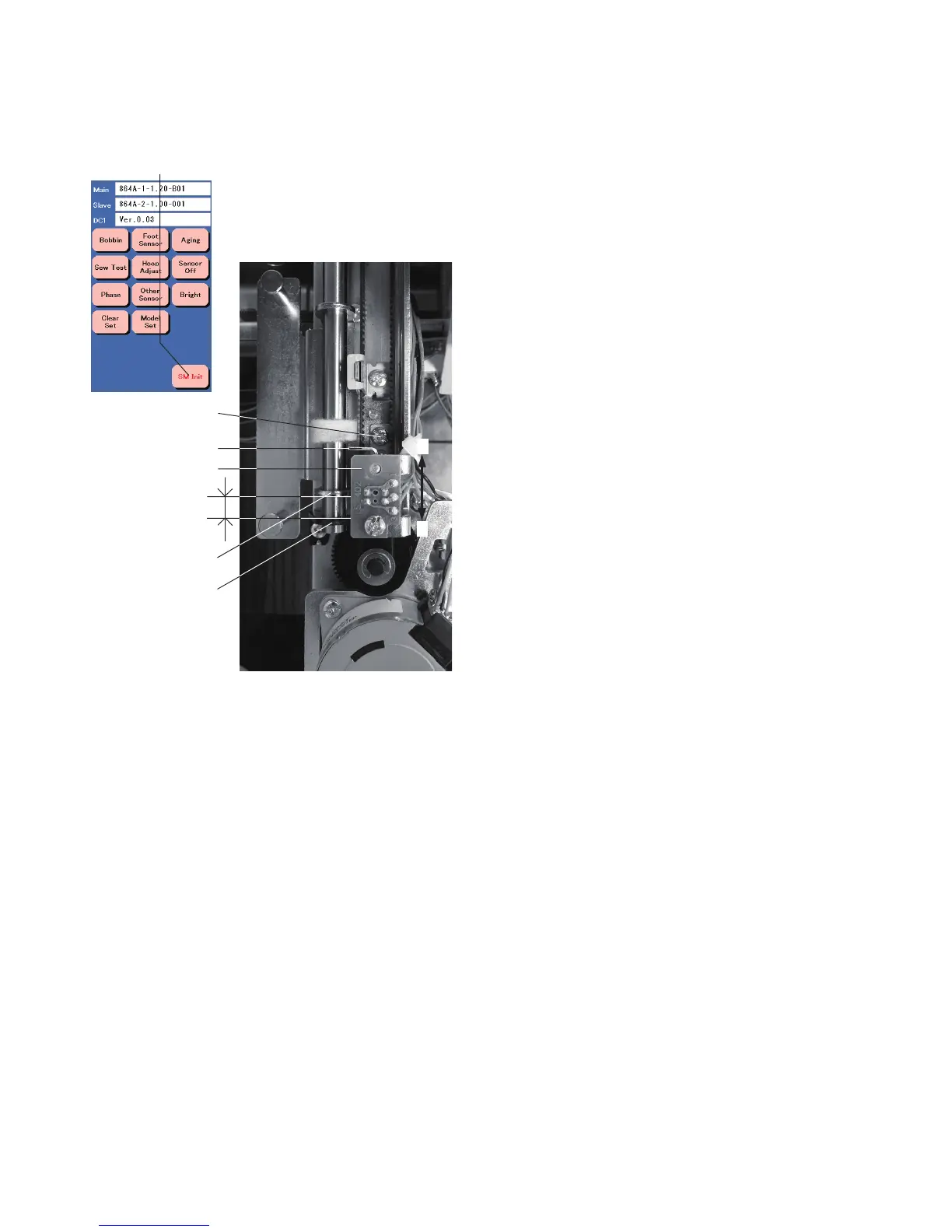
Calibrating the switch for foot position detection.

Automatic Thread Cutter Adjustment

Adjusting automatic thread cutter

Setting distance for thread cutter plate slit and moving cutter.

Remaining Bobbin Thread Sensor Adjustment

Adjusting bobbin thread sensor

Calibrating the sensor for bobbin thread levels.

Hoop Adjustment

Adjusting hoop position

Aligning hoop with the template hole.

Replacing the Carriage Unit

Replacing carriage unit

Procedure to remove and install the carriage unit.

X-sensor Position Adjustment

Adjusting X-sensor position

Setting the gap between stopper and X-carriage guide.

Y-sensor Position Adjustment

Adjusting Y-sensor position

Setting the gap between hoop base and Y-shaft plate.

Adjusting the Y-carriage Supporter

Adjusting Y-carriage supporter

Setting distance between rail and Y-carriage edge.

Replacing the Switching Power Supply

Replacing switching power supply

Procedure to remove and install the switching power supply.

Replacing Driving Motor

Replacing driving motor

Procedure to remove and install the driving motor.

Replacing the Gear of the X-carriage

Replacing X-carriage gear

Procedure to replace gears in the X-carriage.

Oiling the Machine (1)

Oiling needle bar, presser bar, thread take-up lever

Oiling points for needle bar, presser bar, and take-up lever.

Oiling the Machine (2)

Oiling the oil wick

Oiling procedure for the oil wick.

Oiling the lower shaft supporter (front and rear)

Oiling points for the front and rear lower shaft supporters.

Oiling the Machine (3)

Oiling the Y-carriage

Oiling points for the Y-carriage.

Oiling the X-carriage

Oiling points for the X-carriage.

Related product manuals