Page: 6
FM-200® FILL MANUAL
Revision B
Document # DOC180
Issued: August 16, 2010
Revised: April 2, 2012
Section 2 Cylinder Assembly
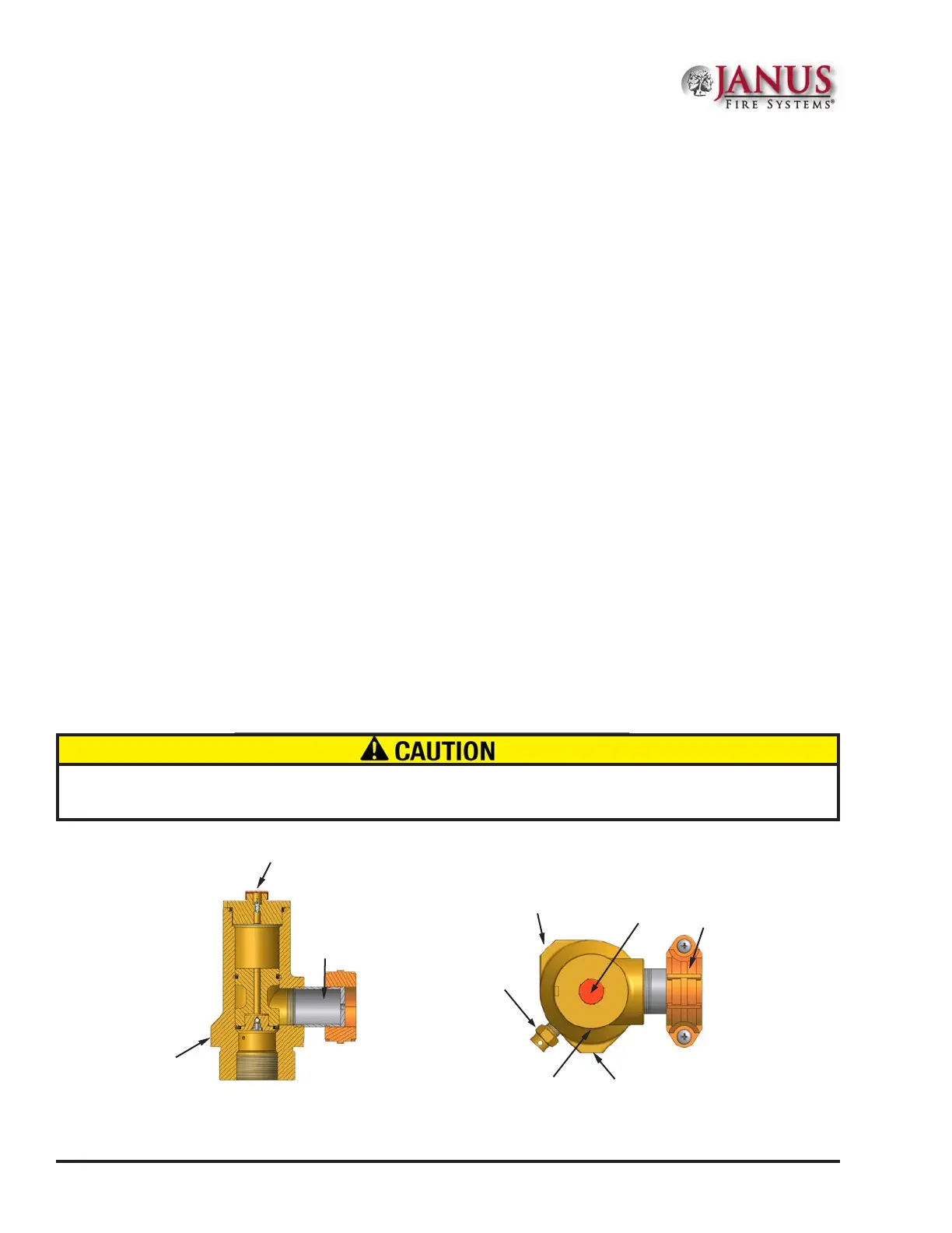
2.3.2 Mv Series Valve Features
(See Figure 2.3.2)
e Mv Series cylinder valve has six key features:
1. Valve Actuation Connection: A threaded connection located on top of the cylinder valve serves as the
attachment point for the electric (primary) or pneumatic (slave) valve actuator.
2. Pressure Gauge Connection: A female connection serves as the attachment point for the pressure
gauge. It is tted with a Schrader valve to allow the removal of the gauge while the cylinder is
pressurized.
3. Low-Pressure Supervisory Switch Connection: A female connection serves as the attachment point
for the low-pressure supervisory switch. A Schrader valve allows for the removal of the pressure switch
while the cylinder is pressurized.
4. Rupture Disc: A frangible rupture disc is tted to the valve body opposite the discharge outlet. It
functions as an emergency relief device in the event of excessive internal pressure within the cylinder.
Its rupture point is between 850 psi (58.6 bar) and 1000 psi (68.9 bar). e rupture disc shall not be
removed while the cylinder is under pressure.
5. Discharge Outlet: A 2 in (50 mm) grooved connection serves as the attachment point for discharge
piping.
6. Pilot Actuation Port: A 1/4 in (8 mm) NPT connection (shipped with a pipe plug) serves as the
attachment point for the pilot actuation piping in multiple cylinder systems, providing the actuation
pressure used to open the slave cylinder valve(s). is can also be used for attachment of the discharge
pressure switch in single cylinder arrangements. e pipe plug shall remain in place at all times when
the port is not connected to pilot actuation piping or a discharge pressure switch.
Figure 2.3.2 Mv Cylinder Valve Assembly
Pressure Gauge
Connection (2)
Grooved
Coupling (Part
of Anti-Recoil
Safety Device)
Low-Pressure
Supervisory Switch
Connection (3)
Pilot Actuation
Port (6)
Safety
Cap
Rupture
Disc (4)
Valve Actuation
Connection (1)
Discharge
Outlet (5)
Pressure Gauge
Connection (2)
Ensurethatthepilotactuationportpipeplugisinplacebeforeattemptingtollthecylinderassembly.Failureto
dosomayresultinagentleakingoutofthepilotactuationportduringthellprocedure.
 Loading...