Page: 50
FM-200® FILL MANUAL
Revision B
Document # DOC180
Issued: August 16, 2010
Revised: April 2, 2012
C LIQUID LEVEL INDICATOR REPLACEMENT
e following steps detail the procedure for removing and replacing the liquid level indicator.
1. Pump down the cylinder. ENSURE THAT THE CYLINDER IS COMPLETELY EMPTY AND
DEPRESSURIZED BEFORE CONTINUING.
1. Remove the cylinder valve and dip tube by lifting straight up and
out. Be careful not to damage the cylinder valve threads.
Note: When removing the Lv Series cylinder valve and dip tube
assembly, an overhead lift may be required for removal or else two
people working together on an elevated platform.
2. Remove the liquid level indicator (LLI) by using a 1-1/8 inch wrench
on the hex nut directly above the LLI boss on the cylinder. (Refer to
Figure C.1)
3. Once the hex nut threads are backed out, SLOWLY pull the LLI out from
the cylinder boss. e ball oat at the base of the LLI rod will not allow for
the LLI to be completely removed. Care should be taken to avoid damaging
the ball oat or the stop clip when withdrawing the LLI. (Refer to Figure
C.2)
4. While the LLI rod is held extended from the LLI boss, reach into the
cylinder through the cylinder collar to locate the ball oat and stop washer
at the base of the LLI rod. SEE NOTE 1.
5. Pinch the stop clip with forenger and thumb with enough force to slide
both the stop washer and ball oat o of the LLI rod. Be careful not to
drop the ball oat or washer into the cylinder. If the stop washer cannot
be removed easily, it can be cut with snips. A cut or damaged stop washer
should be replaced with a new washer when reinstalling the LLI assembly.
6. Pull the ball oat and stop washer out of the cylinder through the cylinder
collar opening. e LLI rod should now be easily removed from the LLI
boss.
7. Remove the old o-ring with a pick and destroy it to avoid reuse. Clean the
LLI o-ring groove, making sure there is no debris that could score or cut
the new o-ring. Any dust, dirt, weld slag, metal shavings, paint over-spray,
etc., must be removed before reinstallation. Lightly lubricate the o-ring
groove with Molykote 55 by Dow Corning or equivalent.
8. Lubricate the new o-ring with Molykote 55 by Dow Corning or equivalent.
Use painters tape or masking tape around the LLI threads before installing
the new o-ring to avoid any cutting or scoring of the new o-ring. Remove
painting/masking tape after the o-ring is positioned correctly.
Hex Nut
LLI Boss
Figure C.1 LLI Exterior
NOTE 1 – A washer may not be present depending on the date the LLI assembly was manufactured. If the LLI assembly does not have a
washer, one should be obtained and placed onto the assembly when indicated during this procedure.
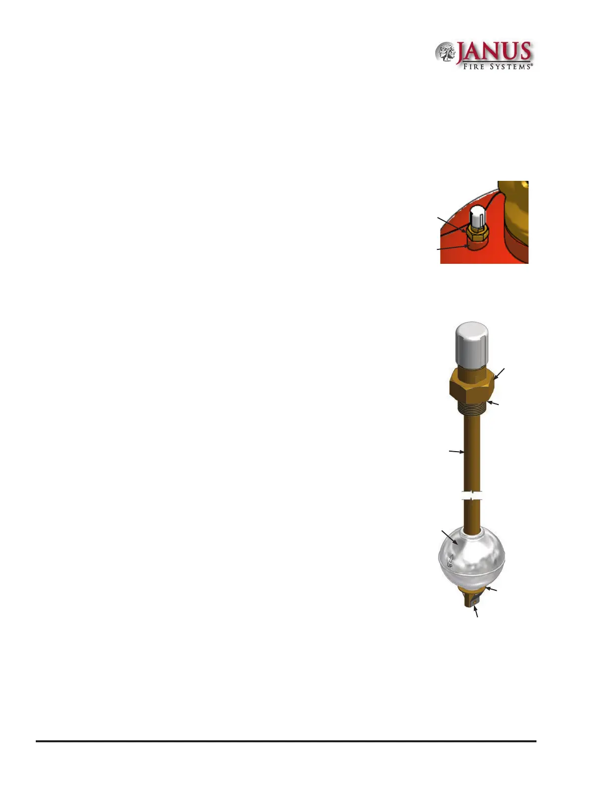
Ball Float
Stop Clip
Stop Washer
LLI
Rod
Hex Nut
Figure C.2 LLI Interior
O-Ring
Location
Appendix C
 Loading...