SAFETY INFORMATION
Warning
Caution
Leakage/Resistance Check
Critical Components
List of Safety Components Requiring
Exact Replacements
DBR Bridge diode. Use only factory replacement.
C1, 2
C6
Faceplate
Air leak cover
CMC1
L1
Fuse PCB
Main PCB
Faceplate. Use only factory replacement
10uF 50V electrolytic redial
See Page 16 Service Bulletin
SB2AMI Power output module. Use only factory
replacement
4700uF,50V electrolytic filter caps. Be sure
replacement part is at least the same
working voltage and capacitance rating.
Also the lead spacing is important.
Incorrect spacing may cause premature
failure due to internal cabinet pressure and
vibration.
2
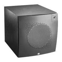
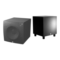
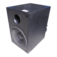
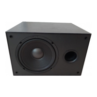
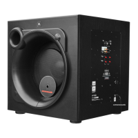
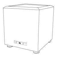
Amplifier/Subwoofer PSW-D110/DPS-10
F1
PWRCORD
TRX1 Transformer. Use only factory replacement.
SPT-2 or better with polarized plug, UL
approved wire with the hot side to fused
side. Use with factory replacement panel
strain relief only.
Fuse SLO BLO 1.25A 250V UL approved
Any person performing service of this unit will be exposed
to hazardous voltages and the risk of electric shock. It is
assumed that any person who removes the amplifier from
this cabinet has been properly trained in protecting against
avoidable injury and shock. Therefore, any service
procedures are to be performed by qualified service
personal ONLY!
Before returning the unit to the customer, perform a
leakage or resistance test as follows:
Leakage Current. Note there is no power switch on this
unit. When the power plug is plugged in, the unit is live.
Connect the unit to its rated power source. Using an
ammeter, measure the current between the neutral side of
the AC supply and chassis ground of the unit under test. If
leakage current exceeds 0.5A, the unit is defective.
Reverse the polarity of the AC supply and repeat.
Resistance. Measure the resistance from either side of the
line cord to chassis ground. If it is less than 500k ohms, the
unit is defective.
WARNING! DO NOT return the unit to the customer if it
fails one of these tests until the problem is located and
corrected.
This unit does not have a power switch. Hazardous
voltages are present within the unit whenever it is
plugged in.
Before the amplifier is plugged in, be sure its rated voltage
corresponds to the voltage of the AC power source to be
used. Incorrect voltage could cause damage to the
amplifier when the AC power cord is plugged in. Do not
exceed rated voltage by more than 10%: operation below
90% of rated voltage will cause poor performance or may
shut the unit off.
00465
IMPORTANT SERVICE NOTES: When testing the PSW-D110/DPS-10 Series amplifier, a load must always be
connected to the output terminals, whether the woofer, or a 4 to 8 ohm resistive load.
All AC powered test instruments (meters, oscilloscopes, etc.) must have a floating ground, i.e., be
connected to an isolation transformer.
All components identified with the IEC symbol
in the parts list and the schematic diagram
designate components in which safety can be
of special significance when replacing a
component identified with . Use only the
replacement parts designated in the parts list or parts with
the same rating of resistance, wattage or voltage.
Use only factory replacement
Use only factory replacement
Use only factory replacement
Use only factory replacement
Use only factory replacement
 Loading...