26
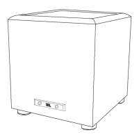
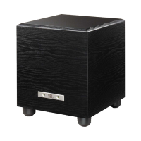
Amplifier/Subwoofer PSW-D110/DPS-10
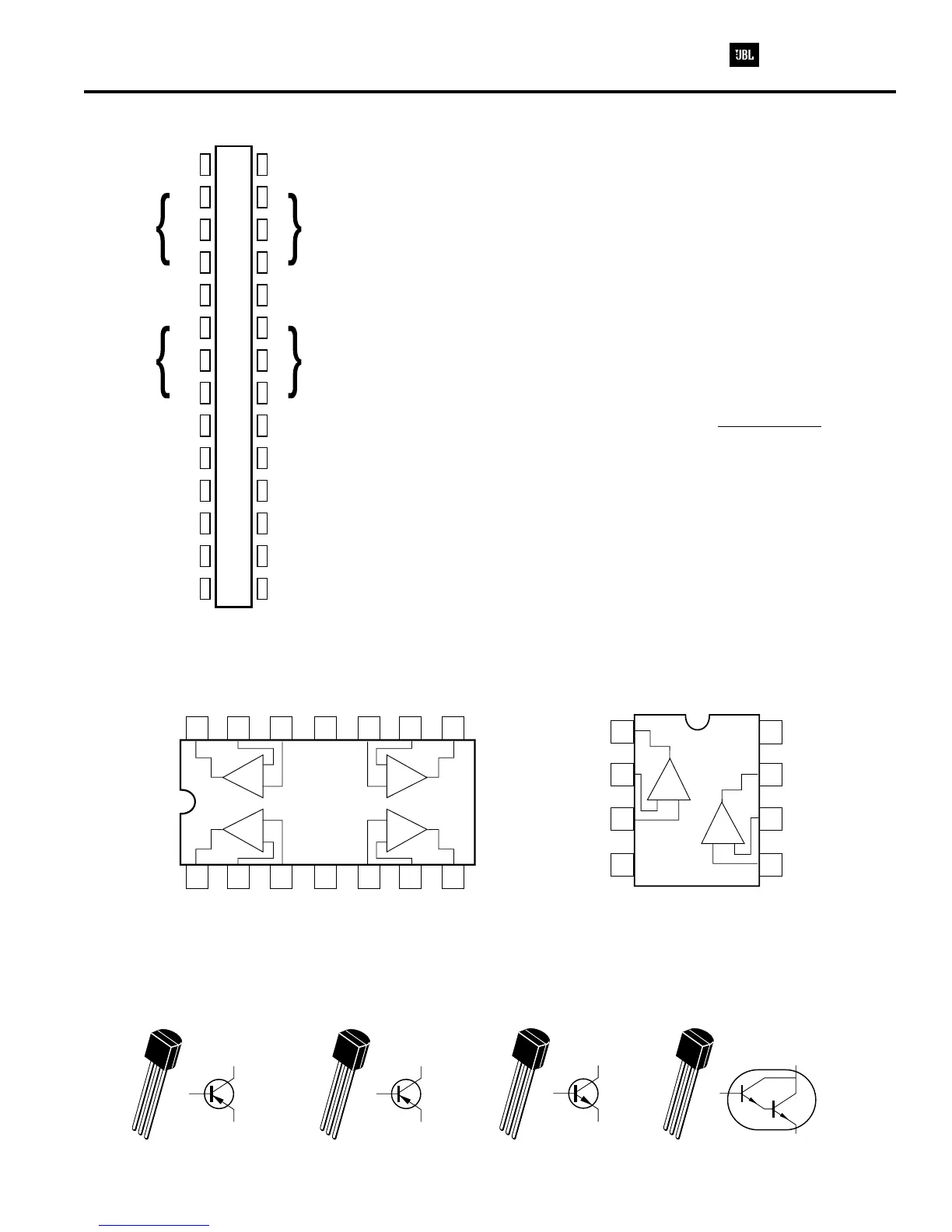
PSW-D110/DPS-10 INTEGRATED CIRCUITS
U1-(LM324) Quad Op Amp
U2, U3 - (TLO 82) Dual Op Amp
15
26
37
4
14 10
13 9
12 8
11
12
43
-
-
-
-
+
+
+
+
OUT 4
OUT 1
IN 4
-
IN 1
-
IN 4
+
IN 1
+
GND
V+
IN 3
+
IN 2
+
IN 3
-
IN 2
-
OUT 3
OUT 2
2
Base
2
Base
3 Collector 3 Collector
1 Emitter 1 Emitter
11
22
33
Q4, 5 - (MPS A56)
80V PNP Transistor
Q2 - (2N3906)
40V PNP Transistor
2
Base
2
Base
3 Collector 3 Collector
1 Emitter
1 Emitter
11
22
33
Q3 - (2N3904)
40V NPN Transistor
Q1 - (MPS A13)
30V NPN(Darl) Transistor
S53AMI/S64AMI - Power Amp module SAFETY PART
15
16
17
18
19
20
21
22
23
24
25
26
27
28
1
2
3
4
5
6
7
8
9
10
11
12
13
14
+6V
v+
O/P
V-
+15V
SD
FR
I/P
GND
-15V
+6V
v+
O/P
V-
+15V
SD
FR
I/P
GND
-15V
NOTE: THE FOLLOWING PROCEDURES MUST BE FOLLOWED
WHEN INSTALLING NEW S53AMI/S64AMI AMP MODULES:
FAILURE TO FOLLOW ONE OR MORE OF THESE STEPS MAY
RESULT IN THE INSTANT DESTRUCTION OF THE MODULE WHEN
POWERED UP.
Align white indent marker on Amp Module with indent marker on main
PCB; alternately observe position of label on the top of the module;
incorrectly replacing the Module 180 in the PCB slot will result in its
destruction.
All AC powered test instruments (meters, oscilloscopes, etc.) must
have a floating ground, i.e. be connected to an isolation transformer.
Align and position the Amp Module before soldering.
Attach the amp Module with the mounting screws or
powering up.
Use only rosin-core or non-acid core solder; thoroughly de-flux the
surfaces after soldering.
If the new S53AMI/S64AMI Amp Module has larger mounting hole(s) in
the case, and the stock screws no longer will fit, and screws of the
proper type cannot be obtained locally order:
(2) part# 60301S (screws)
(2) part# 60301N (nuts)
°
before soldering
1)
2)
3)
4)
5)
1
2
3
4
8
7
6
5
A
B
-
-
+
+
B OUTPUT
A OUTPUT
B -INPUT
A -INPUT
B +INPUT
A +INPUT
V
-
V
+
 Loading...