15 - 2
Descriptions (cont'd)
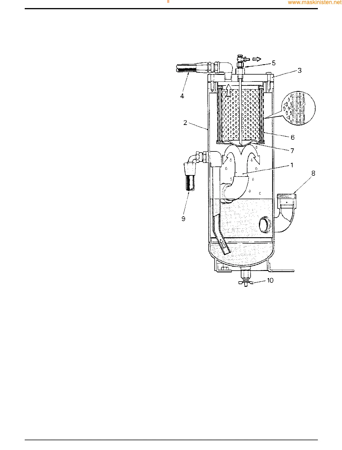
Oil Separation and Recovery
The air/oil receiver separates the oil from the air/oil mixture
after compression has taken place and acts as an oil
reservoir.
The receiver consists of a vertical steel casing 2 constructed
in accordance with the appropriate standards for fusion
welded pressure vessels and contains a separator 6.
Access to the separator is provided by cover 3. Fitted in the
cover is a temperature sensor, air pressure gauge feed, oil
scavenge tube 5 and air delivery pipe 4 terminating at the
delivery manifold. Receiver fittings include an oil filler
plug/dipstick 8, drain tap 10 and safety valve (not shown).
The air/oil mixture 1 from the compressor enters the receiver
through an angled connection which directs the mixture
against the bottom of well 7. The resulting sudden change in
speed and direction of the flow causes most of the oil to
drop out under gravity to the bottom of the casing where it
re-joins the main oil flow and is re-circulated.
The air which now holds only a small amount of fine oil mist
then flows through the separator 6 where the mist is
agglomerated into large droplets which collect in well 7.
From there the collected oil is returned via the oil scavenge
tube 5 to the compressor by differential pressure.
Component Key
Item Description
1 Air/oil mixture (from compressor)
2 Receiver casing
3 Cover
4 Air delivery pipe
5 Oil scavenge tube and restrictor
6 Separator element
7 Well
8 Oil filler/dipstick plug
9 Oil feed to cooler
10 Drain tap
Section A Attachments
9803/7130
Section A
15 - 2
Issue 1
Airmaster Compressor
S212050