A201040
2 - 2
Circuit Description
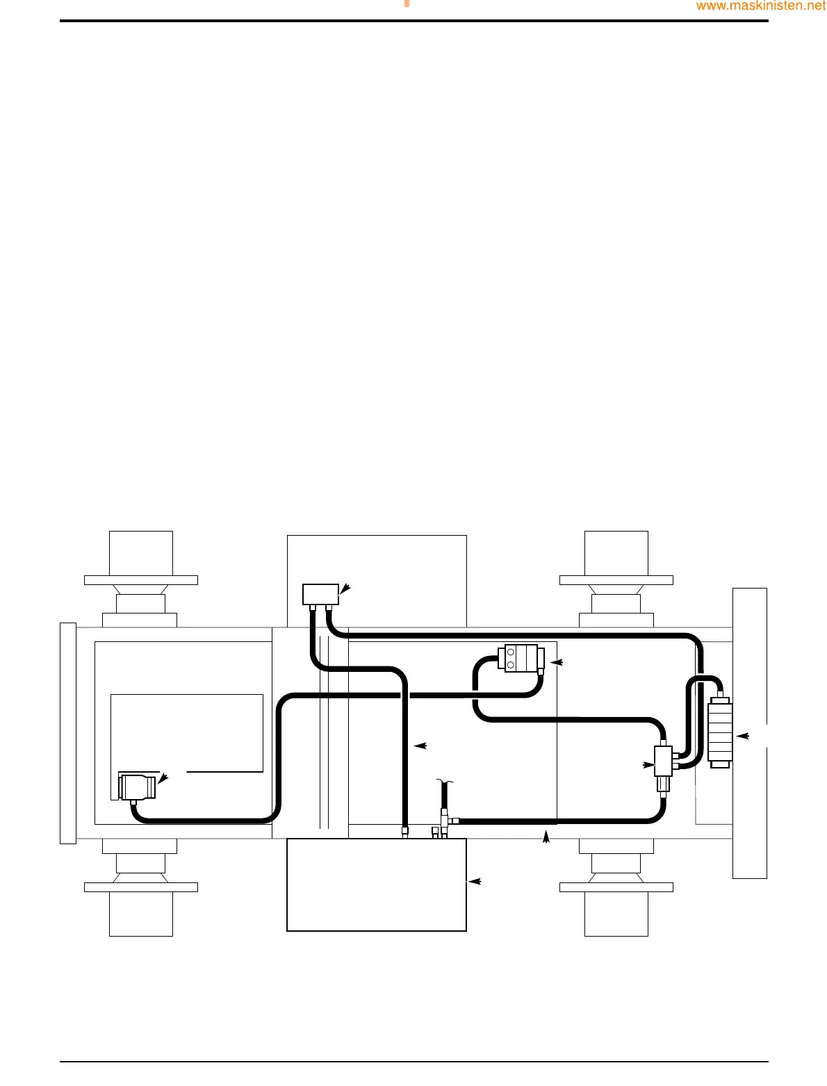
Oil from the hydraulic pump 2 enters the loader valve 3 (brake and steer circuits not shown). From the loader valve, the oil
passes to flow diverter valve 8. This valve establishes a priority (and controlled) flow to the hydraulic tool circuit (HTC), if the
hydraulic tool circuit (HTC) has not been selected, the oil passes from port B of valve 8 to the backhoe valve 4. From the
backhoe valve the oil returns to the hydraulic tank 1 via an in-line filter (not shown).
When the hydraulic tool circuit (HTC) is selected, a solenoid inside the diverter valve 8 is energised, this causes the flow of oil
inside the valve to be diverted to port P and on to the hydraulic tool circuit (HTC) via quick release couplings 6. Oil returning
from the circuit returns directly to tank 1 via hose C. The flow of oil from port P is regulated regardless of changes in load
pressure or pump flow. Any excess flow (anything over 20 litres/min) is distributed to port B for use in other actuators (e.g.
backhoe valve).
The diverter valve 8 also incorporates a relief valve, when the pressure in the priority circuit (port P) exceeds the setting of the
relief valve all oil flow is returned directly back to tank via hose D.
Section A Attachments
9803/7130
Section A
2 - 2
Issue 1
Hydraulic Tool Circuit (H.T.C.)
22
33
88
44
11
CC
DD
66
 Loading...