61 - 2
Dismantling and Assembly
The numerical sequence shown on the illustration is
intended as a guide to dismantling.
For assembly the sequence should be reversed.
Great care should be taken when dismantling and
assembling a valve to avoid the following:-
Contamination
Damage to spools
Damage to seal grooves
Any of the above may result in possible problems with the
operation of the valve.
Dismantling
When removing 'O' Rings and seals, use an appropriatly
rounded tool that WILL NOT cause any damage to the seal
grooves.
Discard ALL 'O' Rings. DO NOT use worn or damaged
items.
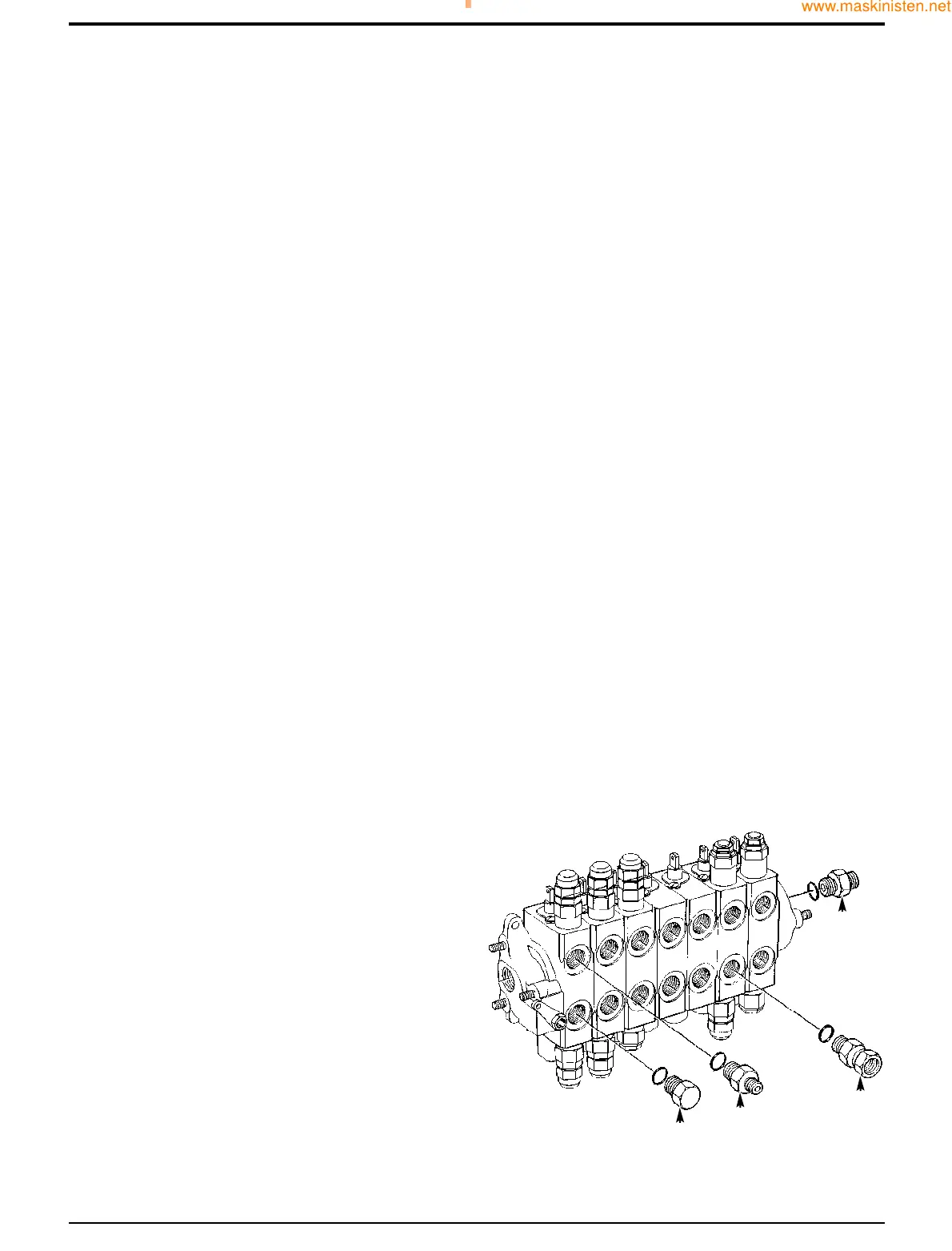
Check Valves
Each of the identical load hold check valves 4R to 4W can
be removed as shown at 4W. Note only 4W shown on
illustration.
Ensure good condition of seating face on poppet 10 and on
the mating face in the valve block.
Note: Valve block adapters, types A, B, C and D are torqued
to 81 Nm (60 lbf ft; 8.3 kgf m).
Spools
Spools 4B, 4C, 4D, 4E and 4F are identical but must not be
interchanged as they are matched to their bores. Slew spool
4A is different in design from the above spools.
All spools have the same centring and sealing components
items 11 to 19 and 24 to 27.
To completely dismantle a spool, follow the sequence 11 to
19 and 24 to 27. To prevent spool rotation when turning
screw 13, hold a rod through the eye end of the spool.
Inspection
Inspect the valve components for scratches, nicks or any
other type of damage, replace with new if required.
Assembly
Renew all 'O' rings.
Lubricate new seals with JCB Hydraulic Fluid and take care
to prevent them from being damaged by the sharp edges of
the spool.
Apply JCB Threadlocker and Sealer to threads of screw 13.
Section E Hydraulics
9803/7130
Section E
61 - 2
Issue 1
Excavator Valve
S205350
DD
CC
BB
AA
Torque Settings
Item Nm kgf m lbf ft
1A 17.6 - 20.4 1.76- 2.04 13 - 15
1B 41 - 49 4.2 - 5 30 - 36
11 6.1 - 7.5 0.62 - 0.76 4.5 - 5.5
13 9.5 - 10.9 0.97 - 1.11 7 - 8
22 41 - 68 4.15 - 6.9 30 - 50
Relief Valves
Ensure that A.R.V's 4H to 4P are correctly adjusted and
fitted in their specified positions.
Torque tighten A.R.V's 4H, 4J, 4K and 4N to 41 - 68 Nm (30
- 50 lbf ft, 4.15 - 6.9 kgf m).
Torque tighten A.R.V's 4L, 4M and 4P to 41 - 68 Nm (30 - 50
lbf ft, 4.15 - 6.9 kgf m).
For relief valve dismantling and assembly procedure, refer to
Excavator Valve, Dismantling and Assembly - ARV’s.
 Loading...