32 - 1
The loader control knob houses a microswitch which
energises the transmission dump solenoid.
Make sure that all electrical connections are clearly labelled
before removing the microswitch.
Dismantling and Assembly
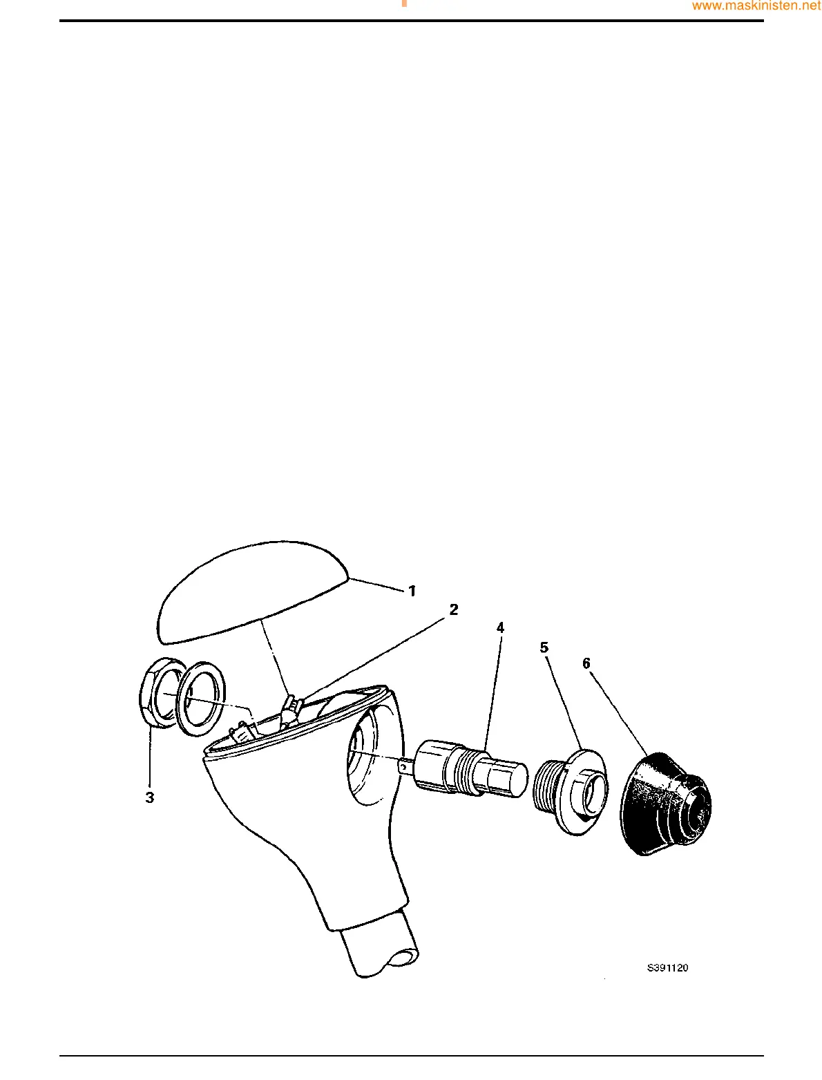
The numerical sequence shown on the illustration is
intended as a guide to dismantling.
For assembly the sequence should be reversed.
Dismantling
To gain access to the microswitch gently prise off top cover
1. Disconnect wiring harness 2, remove locknut 3 and
shakeproof washer. Microswitch 4, adapter 5, and rubber
cover 6 may now be withdrawn through the knob.
Assembly
Apply JCB Threadlocker and Sealer to microswitch adapter
5 prior to assembly.
Note: Microswitch 4 is a non-service item, and must be
replaced as an assembly.
Section D Controls
9803/7130
Section D
32 - 1
Issue 1
Loader Control Knob
 Loading...