14
Please see operator manual for full details.
Shutdown & Auxiliary Venting
1
4
2 3
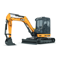
Park Machine
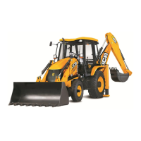
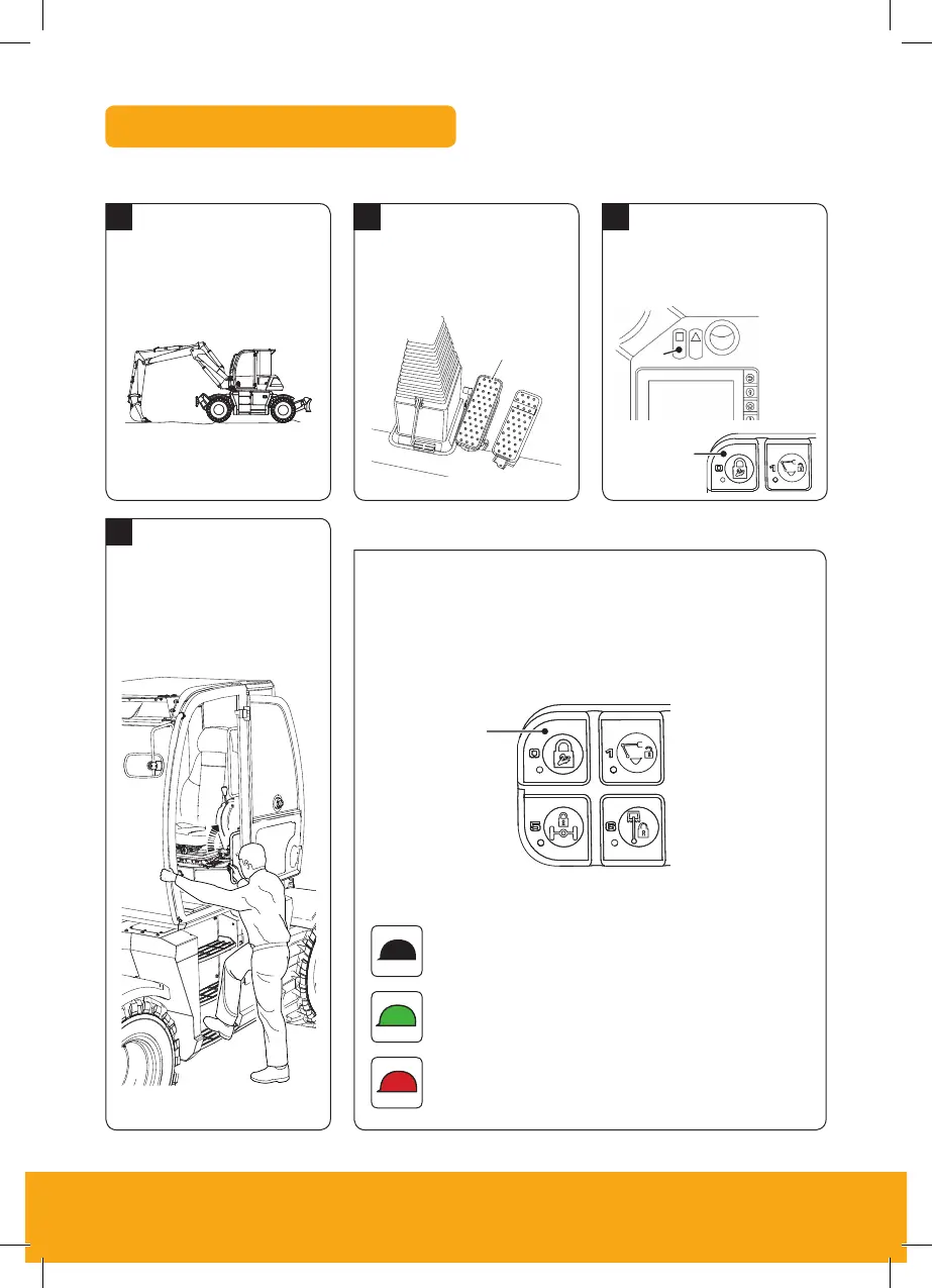
Exit Cabin
Apply Foot Brake
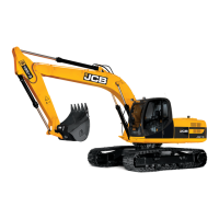
Emergency Lowering
Secure Machine
Ensure machine slew is central
and attachment on the ground.
Switch off all switches. Leave
machine using the handrails
and footholds.
Park machine and apply foot
pedal (A) until it locks.
1. Make the machine safe
2. Turn the ignition key to the on position
3. Press and hold 2Go button (A), buzzer will sound
4. Operate controls to lower boom to safe position / auxiliary vent
5. Emergency lowering will last for a short duration
Black Helmet – Hydraulics isolated
Green Helmet – Hydraulics active
Red Helmet – Emergency lowering. (Press and hold the
2 Go switch (A) for 3 seconds until the red LED illuminates
Apply park brake (A) and
disable hydraulics (2 Go) (B).
Auxiliary Venting
B
About the Product
Console Switches
20 9831/3350-2 20
Console Switches
General
The console switches may change according to machine specification. Some are used for machine options.
Each switch has a graphic symbol to show the function of the switch. Before you operate a switch, make sure
that you understand its function.
The switch LED (Light Emitting Diode) will illuminate to show that the switch function is active.
Figure 17.
1 3 4 5 62
7 9 10 11 128
13 15 16 17 1814
19 21 22 23 2420
1. 2 Go: Push the switch after the isolation lever has been lowered to enable the machine hydraulics. It can
also be pressed independent of the isolation lever to disable/enable the hydraulics. It is also used as the
confirmation button in the Quickhitch release sequence.
1.1. Button can be pressed and held for time specified to activate the hydraulics with a dead engine. The
hard hat symbol illuminates red.
Duration: 3s
2. Quickhitch (option).
Refer to: Instruments (Page 61).
3. Side lights.
4. Front Worklights.
5. Beacon (option).
6. SiteMode/Highway mode: Press the switch to request a change of mode. If in site mode this requests a
change to highway mode (highway mode on). If already in highway mode this requests a change back to
site mode (highway mode off).
Refer to: Getting the Machine Moving (Page 75).
6.1. There are a number of conditions that the machine needs to meet to safely enter highway mode: upper
structure must be slewed to the straight ahead position, reverse steer (if installed) must be switched
off, machine must be stationary. If these conditions are met then the machine will go to highway mode
and the mode indicator at the top left of the display will change to show highway, the dig end controls
will be isolated and the slew lock will be automatically applied.
6.2. If the conditions are not met then the machine cannot safely enter highway mode, the machine will
remain in site mode, the switch LED will flash. A check sheet will appear on the display showing
the operator which conditions are not met. The operator can either meet the outstanding conditions
and the check sheet will disappear and allow the machine to enter highway mode or he can cancel
the highway mode request with a further press of the switch, returning the machine to site mode. To
change from highway mode to site mode the only condition is that the machine is stationary and gear
selected is in neutral.
6.3. Highway/site mode is remembered between key cycles.
7. Axle loc
k: Pressing the switch to cycle through three states i.e., axle lock off, axle lock on and auto axle lock.
The appropriate status indicator appears on the left side of the display. Auto axle lock automatically applies
Operation
Entering and Leaving the Operator Station
31 9831/3350-2 31
Emergency Exit
WARNING Do not obstruct the rear cab window, this is an emergency exit.
The primary exit is the left side cab door and left side steps. It is also possible to exit the machine using the
right side secondary steps. In an emergency, if the machine is stopped at 90° to the chassis the front and rear
chassis step plates can be used.
The machine is fitted with a glazing breaker, it is possible to use the rear cab glass as an emergency exit.
Operation
Drive Controls
60 9831/3350-2 60
Service Brake Pedal
CAUTION Pressing the brake pedal sharply down will cause the brake to lock on. Take care when using
the foot brake while travelling.
A
A
A
Operation
Slopes
80 9831/3350-2 80
Figure 61.

 Loading...