17
Daily Checks (10h) Operator’s Manual Page Ref. Physical/Visual
Tyre pressure check 188-189 Physical
Wheel nuts alignment check 186-187 Visual
Tow hitch condition check 74 Visual
Windscreen washer fluid level check/refill 160 Visual
Oil level check 172-173 Physical
Fuel level check 64 Visual
Coolant quality/level check 218 Visual
Coolant or oil leaks check 172 Visual
Park brake – operation check 184 Physical
Oil level check 172-173 Physical
Service brake operation check 184-185 Physical
Park brake operation check 184 Physical
Brake pressure warning operation check 62 & 171 Physical
Controls isolation safety system operation check 171 Physical
Quickhitch safety system operation check 171 Physical
Neutral start safety system operation check
171
Physical
Overload warning system operation check
171
Physical
Weekly Checks (50h) Check
Engine filter/sedimenter drain/clean
173
Physical
Fuel tank – water & sediment drain
178
Physical
Primary fuel filter drain/clean
181
Physical
Main fuel filter drain/clean
181
Physical
Fuel filler cap check/clean
179
Physical
Radiator clean/check
108 & 183
Physical
Pivot & links lubricate
165
Physical
Battery inspect
193
Visual
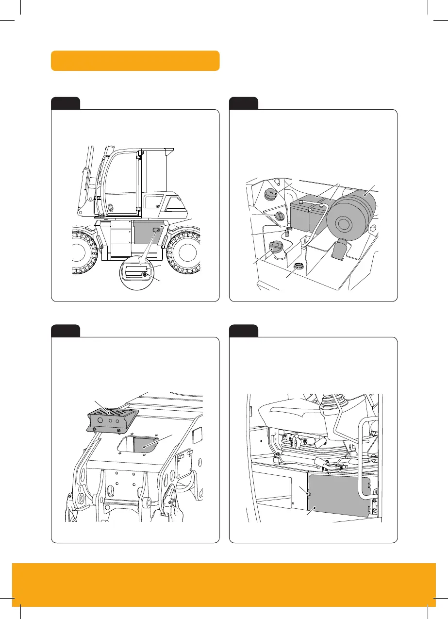
Access Covers
Fig 17
Fig 19
Fig 18
Fig 20
Maintenance
Electrical System
204 9831/3350-2 204
The electrical circuits are protected by fuses. If a fuse blows, find out why before a new one is installed. For
more information on the individual fuses. Refer to: Fuses (Page 256).
Upper Fuses
The fuses are installed in the cab below the operator seat. Remove the thumb screw and open the cover to
get access to the fuses.
Figure 138.
A Cover B Thumb screw
Lower Fuses
The fuses are installed under the tread plate on the front of the chassis. Remove the cover to get access to
the fuses.
Figure 139.
B
A
A Tread plate B Cover
Battery Bay Main Fuse
The main fuse is installed at the back of the battery bay.
Maintenance
Electrical System
204 9831/3350-2 204
The electrical circuits are protected by fuses. If a fuse blows, find out why before a new one is installed. For
more information on the individual fuses. Refer to: Fuses (Page 256).
Upper Fuses
The fuses are installed in the cab below the operator seat. Remove the thumb screw and open the cover to
get access to the fuses.
Figure 138.
B
A Cover B Thumb screw
Lower Fuses
The fuses are installed under the tread plate on the front of the chassis. Remove the cover to get access to
the fuses.
Figure 139.
A Tread plate B Cover
Battery Bay Main Fuse
The main fuse is installed at the back of the battery bay.
A Cover B Handle C Lock
A Tread plate
B Cover (lower fuses)
A Air filter
B Batteries
C Hydraulic oil fill
D DEF fill
E Isolator
F Diesel fill
G Mechanical fuel
gauge
A Cover (upper fuses)
B Thumb screw
A
A
B
B
Maintenance
Service Points
166 9831/3350-2 166
Service Points
General
Figure 118.
A Cooling pack B Engine fuel filter
C Engine oil filter D Engine oil dipstick
E Coolant expansion bottle F Fuel filter/water separator
G Crank case ventilation filter H Engine oil filler cap
Figure 119.
D
C
A
E
G
B
A Fuel filter cap B DEF (Diesel Exhaust Fluid) filler cap
C Battery isolator D Hydraulic oil filler cap
E Battery F Air filter
A
B
D
E
F
G
C
Maintenance
Access Apertures
169 9831/3350-2 169
Access Apertures
General
When moved to their maintenance position, the access panels give you access to parts or areas of the machine
that are not required during machine operation.
Before you operate the machine, make sure that all of the access panels are correctly in their closed or installed
positions.
Battery Cover
Open
1. Make the machine safe.
Refer to: Maintenance Position (Excavator Arm Lowered) (Page 165).
2. Use the ignition key to unlock the cover.
3. Pull the handle to release the latch.
4. Open the cover until it latches in position.
Figure 123.
A
B
C
A Cover B Handle
C Lock
Close
1. To release the latch pull it up.
2. Close the cover.
3. Make sure the cover is closed correctly.
4. Use the ignition key to lock the cover.
A
B
C
Battery Cover
Fuses

 Loading...