8
Please see operator manual for full details.
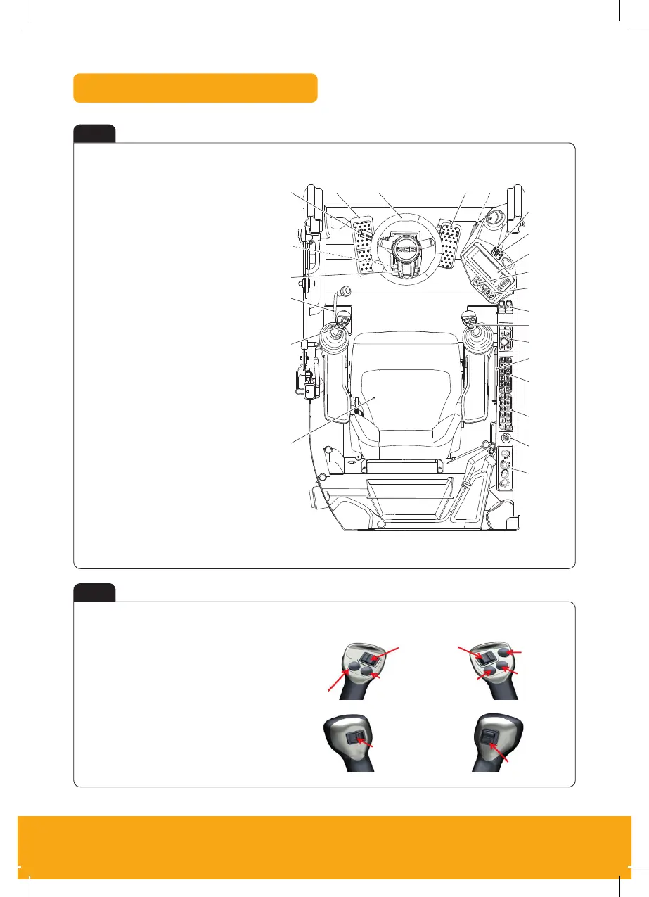
Cab Switch and Panel
Fig 6
Fig 7
A HVAC (Heating Ventilation
Air Conditioning)
B Ignition switch
C Optional switch console
D Switch console
E Fire extinguisher
F Rotary control
G Right joystick
H Stabiliser controls
J Lights and indicators LED
(Light Emitting Diode)s
K 12V socket and USB port
L Instrument panel
M Hazard warning light switch
N Park brake switch
P Throttle pedal
Q Brake pedal
R Steering wheel
S TAB (Triple Articulated
Boom) pedal
T Multi function switch
U Steering column adjustment
V Steer mode selection
W Controls isolator lever
X Left joystick
Y Operator seat
A Low flow auxiliaries 1 and 2
B Horn
C Kingpost swing to high-flow auxiliary
changeover
D King post swing / Hi-flow auxiliary
E Forward / Neutral / Reverse
F Site mode: Boom to dozer changeover
Highway mode: Highway override
G One touch idle
H Hammer
About the Product
Operator Station
16 9831/3350-2 16
Operator Station
Component Locations
Figure 12.
A
B
D
E
A TAB (Triple Articulated Boom) pedal B Steering wheel
C Multi function switch D Brake pedal
E Throttle pedal F Park brake switch
G Instrument panel H 12 volt socket and USB port
J Lights and indicators LED (Light Emitting
Diode)s
K Stabiliser controls
L Right joystick M Rotary control
N Fire extinguisher P Switch console
Q Optional switch console R Ignition switch
S HVAC (Heating Ventilation Air Conditioning)
controls
T Operator seat
U Left joystick V Controls isolator lever
W Steer mode selection X Hazard warning lights switch
Y Steering column adjustment
Figure 13.
A Radio speakers B Radio kit
A
B
C
D
E
F
G
H
J
K
L
M
N
PQRS
T
U
V
W
Y
X
A
H
G
F
E
D
A
B
C
Left Hand Joystick Right Hand Joystick

 Loading...