Jotron AS| TR7750C: Operators Manual Functional description
P/N: 84748 (G)
3 Functional description
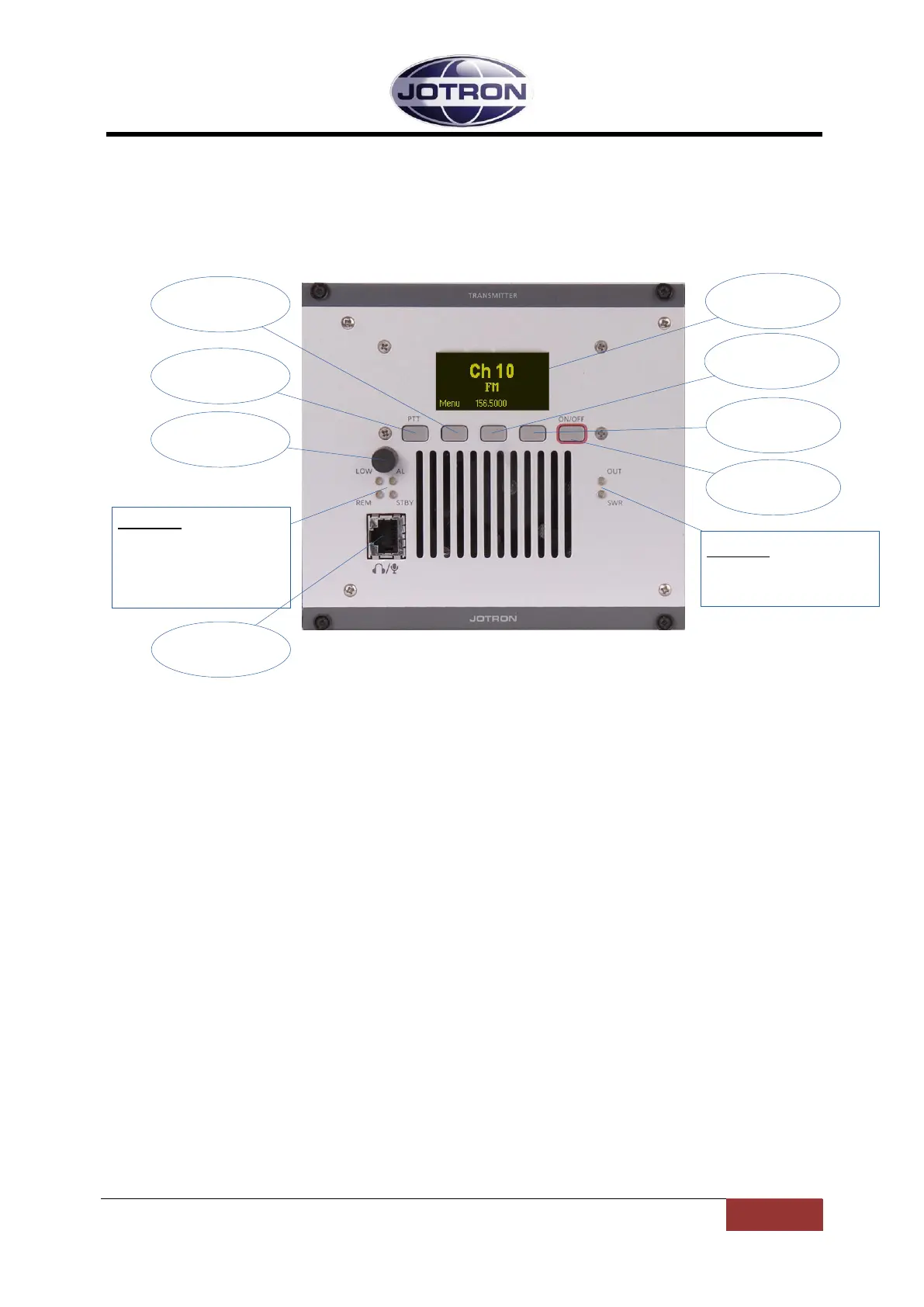
3.1 Front Panel Controls, Transmitter unit
Navigation
button A
Display
Navigation
button B
Indicators:
OUT: Output power indicator
SWR: High SWR indicator
PTT button
Scroll / Select
Switch
ON/OFF
button
Navigation
button C
Indicators:
LOW: Transmits in low power
AL: Alarm active (red)
REM: Remote ready (green)
STBY: Standby (yellow)
Mic/Headset
connector
Figure 3.1-1, Front view, transmitter unit, TA-7650C/25C/10C
3.1.1 Display
The display shows the most important operational parameters; Channel, frequency and modulation.
In addition, the display will show several menus, submenus and operational parameters when
entering into the menu using Navigation button A.
3.1.2 Scroll/Select switch and Navigation buttons A, B and C
The navigation buttons, A, B and C, together with the Scroll/Select switch are used to navigate
through the menus.
The Scroll/Select switch has three actions: It can be turned clockwise, anti-clockwise, or momentarily
pressed.
In general the use of the navigation buttons are:
A or Scroll/Select right: Increase a value (up)
B or Scroll/Select left: Decrease a value (down)
C or Scroll/Select press: Confirm or Enter.
The user interface will indicate which navigation button to use.
3.1.3 PTT button
This button is used to immediately key the transmitter for test/measurement purposes, connected
together with the PTT line available on the microphone connector.
3.1.4 ON/OFF button
Press and hold button (for app. 2s) to switch unit ON or OFF.
 Loading...