Jotron AS| TR7750C: Operators Manual Operating Instructions
P/N: 84748 (G)
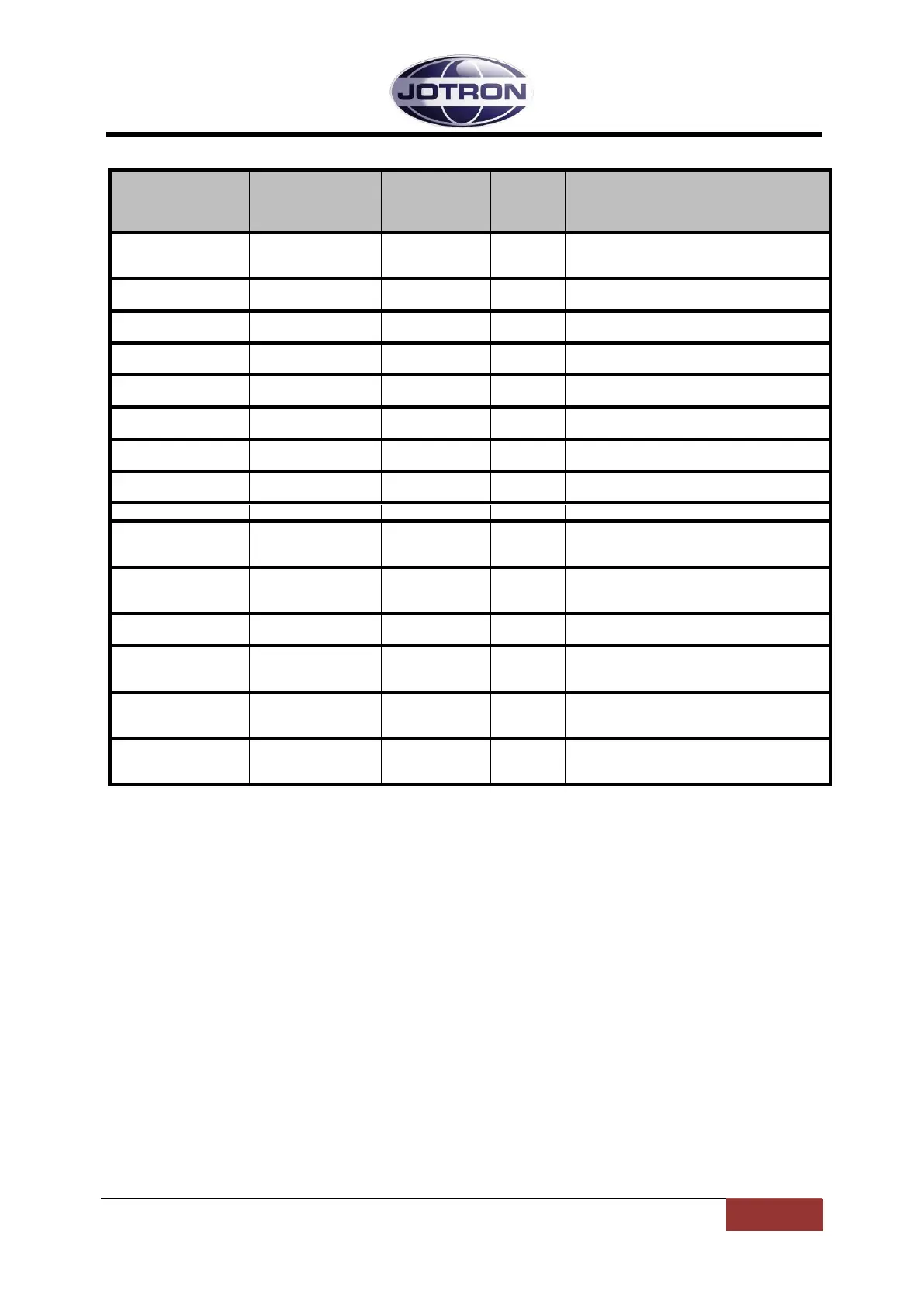
5.5.4 Bite system group
Menu path:
Interface
config ►
Depends on the
alarm status of the
radio unit
This option displays all active alarms in the
unit.
See section 6.1 for more info.
Displays the forward power in dBm detected
at the output of the transmitter
Displays the reflected power in dBm
detected on the output of the transmitter
Displays the calculated VSWR from the
forward and reflected measurements
Displays the measured modulation level on
the output of the transmitter [kHz]
Displays the total current consumption (28V)
of the transmitter [A]
Displays the temperature measured on the
PA module in the transmitter [°C]
Displays the level measured at the output of
the local oscillator in dBm
Displays the input line level in dBm
Displays the regulated 28V supply from the
power regulator board.
The 28V is used on the PA board.
Displays the regulated 12V supply from the
power regulator board
The 12V is used on the main board
Displays the regulated 6V on the modulator
board
Displays the regulated 5V supply from the
power regulator board.
The 5V is used on several modules
Displays the regulated -5V supply from the
power regulator board.
The -5V is used on the main board.
Displays the regulated 3.3V supply from the
power regulator board.
The 3.3V is used on several modules
Table 5.5-4, Bite system group, transmitter
 Loading...