Jotron AS| TR7750C: Operators Manual Functional description
P/N: 84748 (G)
AL (red): Indicates that an alarm is present in the receiver unit. Details of the alarm
will be shown on the display.
REM (green): This LED has multiple functions. The REMOTE indicator will be lit with a
constant green colour when the receiver is “ready” for remote operation.
Ready means that the audio is output to an external source (600 ohm line
input).
In addition the REMOTE indicator will flash yellow each time the unit is
communicating on either of the remote interfaces (RS232, RS485, Ethernet).
STBY (yellow): The receiver is kept in standby, either by user input, an external signal to the
remote interface or because an alarm condition has been detected, and the
receiver is set up as a MAIN receiver. In standby the receiver will not output
any audio on any audio interface.
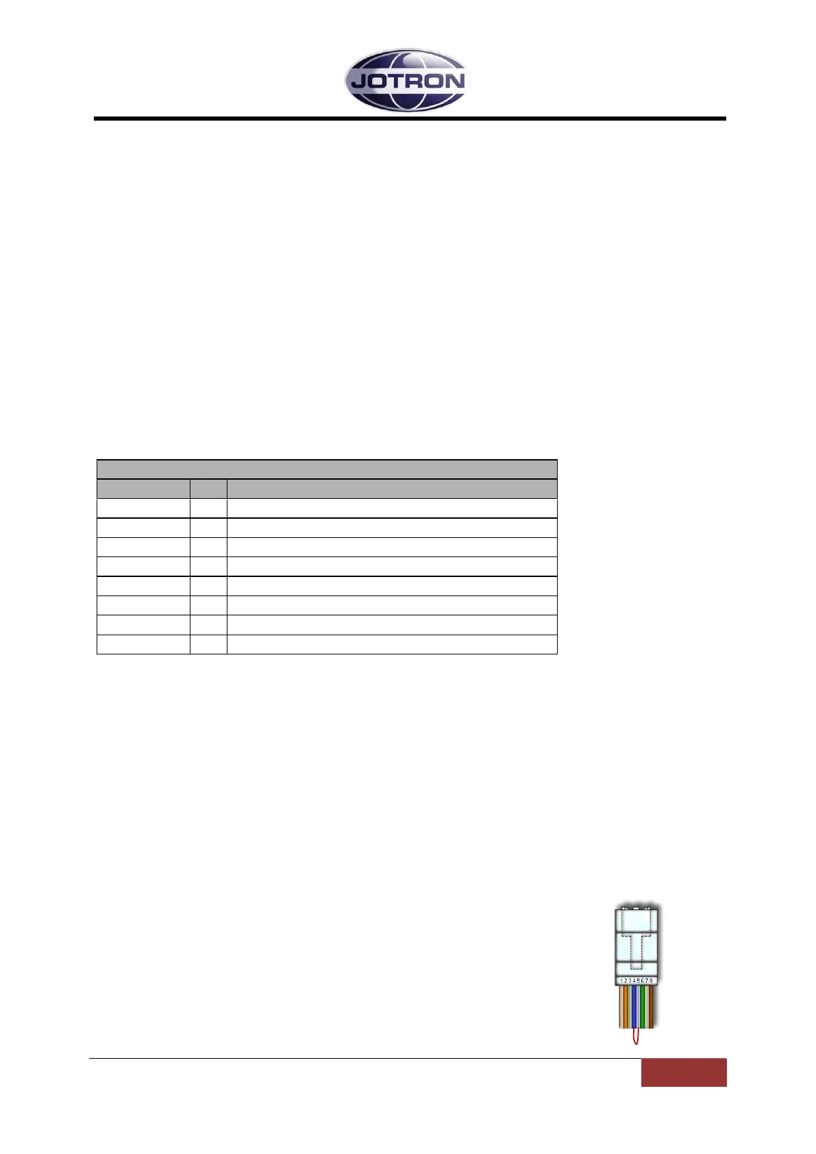
3.3.5 Headset connector
Table 3.3-1, Headset connector, receiver, pin out
The Headset connector is used for multiple purposes:
Headset connector:
The Headset output (referenced to GND) contains the received audio.
RS232 serial line
The RS232serial line that can be used to control radio parameters from an external unit, or to
upload new firmware into the radio unit for future functionality. Details regarding firmware
upgrade is described in the maintenance and repair manual.
Hardware key to change access level: In
order to change the access level (see chapter 5.5.3 for details) a
hardware key must be inserted into the microphone/headset connector before
entering in to the menu system. The hardware key consists of a RJ45
connector where pin no. 4 and 5 (RS232 RX and TX) is connected
together.
Headset output contains received audio.
+12 VDC to external amplifier (10mA)
 Loading...