– 15 –
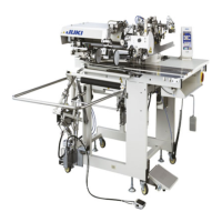
Connector
CN1
Air tube
1A
Air tube
1B
6) Install air tubes coming from the machine head
and the cords coming from the control box to
the position as shown in the gure. At this time,
be careful of the number and alphabet of the
air tubes and the cords. (Adjust the alphabet
of the air tubes to the alphabet of the solenoid
valve. Also, adjust the gures to the gures of
the connector label.)
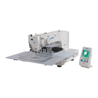
7) Connect air tube
!3
of solenoid valve installing
plate A asm.
!1
to solenoid valve asm.
8
.
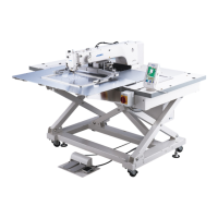
[When using area 1306]
When area 1306 is used, connect the pneumatic components after having carried out
[Connection
common to all areas]
.
!1
Air tube 2B
!5
8) Install the air tubes coming from the machine
head to the joint of solenoid valve installing
plate A asm.
!1
as shown in the gure.
Install two stop plugs
!6
supplied as accesso-
ries to
!4
and
!5
.
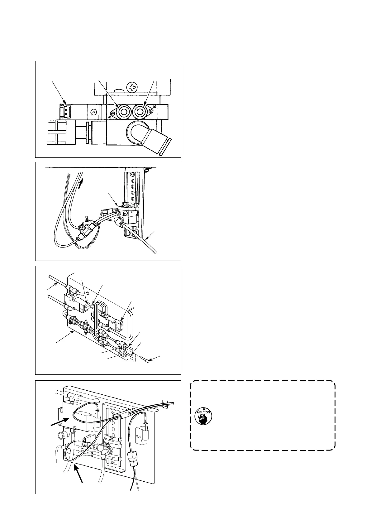
Install cords (CN2, CN3, CNS) coming from the
control box to the solenoid valve.
If a cable has a slack, x the cable on
the table by means of a stapler sup-
plied with the unit.
At this time, provide the cable with an
adequate play (allowance) to prevent
the related connector from being ap-
plied with an excessive load.
CN3
!4
!6
Air tube 2A
!3
CN2
CNS
8
!3

 Loading...