Operation manualⅠ
1-2
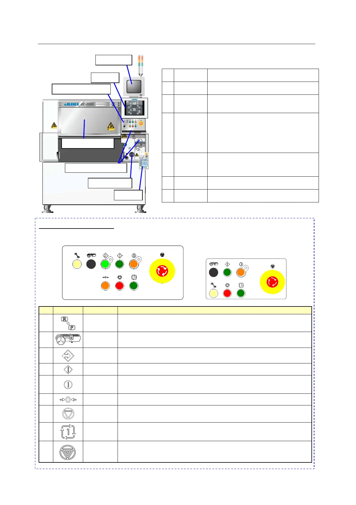
1.2 Configuration of the machine
① Monitor This is a monitor for teaching operation. It
displays an image shot by a camera.
② LCD This is a liquid crystal monitor. It displays
each operation screen.
③ Operation
panel
This is a collection of switches that operate
the machine. (See “Operation panel”
below.)
④ Safety
cover
When you open this cover while the
machine is operating during PWB
production, the machine stops immediately
or stops after it moves its devices to the
desired positions respectively. When you
operate the machine although this cover
opens, the machine operates at low speed.
⑤ - Keyboard
- Mouse
These devices operate each screen
displayed on the LCD.
Operations of these devices are similar with
those of a personal computer.
⑥ Main
switch
This switch turns on or off the power of the
machine.
⑦ HOD This device positions an image shot by a
camera (that is teaching operation).
✡
Operation panel ✡
<FRONT panel > < REAR panel >
No
Switch
Name Function
1
Keyboard
Switches the side on which the switches can be operated, <FRONT> or
<REAR>.
(When the optional rear operation unit is used)
2
Feeder
Switches whether a feeder unit is enabled or disabled.
(When the optional non-stop operation function is used)
3
Online
Use to allow the machine to connect to the IS or the HLC (enter the online status).
The switch lights up when the machine enters Online mode.
4
Start
This is the switch for start。Use to start an actual production run.
5
Servo free
Use to free the servo motor (X-axis, Y-axis, Z-axis, and q-axis).
The switch lights up when servo motor is set into the free state.
The motor is energized again when the switch is pressed the second time.
6
Origin
Use to zero all the axes.
7
Pause/Stop
Use this switch to terminate PWB production or another operation.
Press the switch once to put the production run in a pause status. Press the
switch the second time to stop the production run.
8
Single cycle
Use to stop the production run when one board has been produced.
Press the switch a second time to exit from this status.
9
Emergency
This is the switch for emergency stop.
Use this switch to immediately stop the machine when it malfunctions or when
it may pose risks to your safety. When you turn it in the direction indicated
with the arrow mark, the machine is recovered from this emergency stop state.
① Monitor
② LCD
③ Operation panel
⑤ Keyboard/ Mouse
④ Safety cover
⑥ Main switch
⑦HOD
 Loading...


