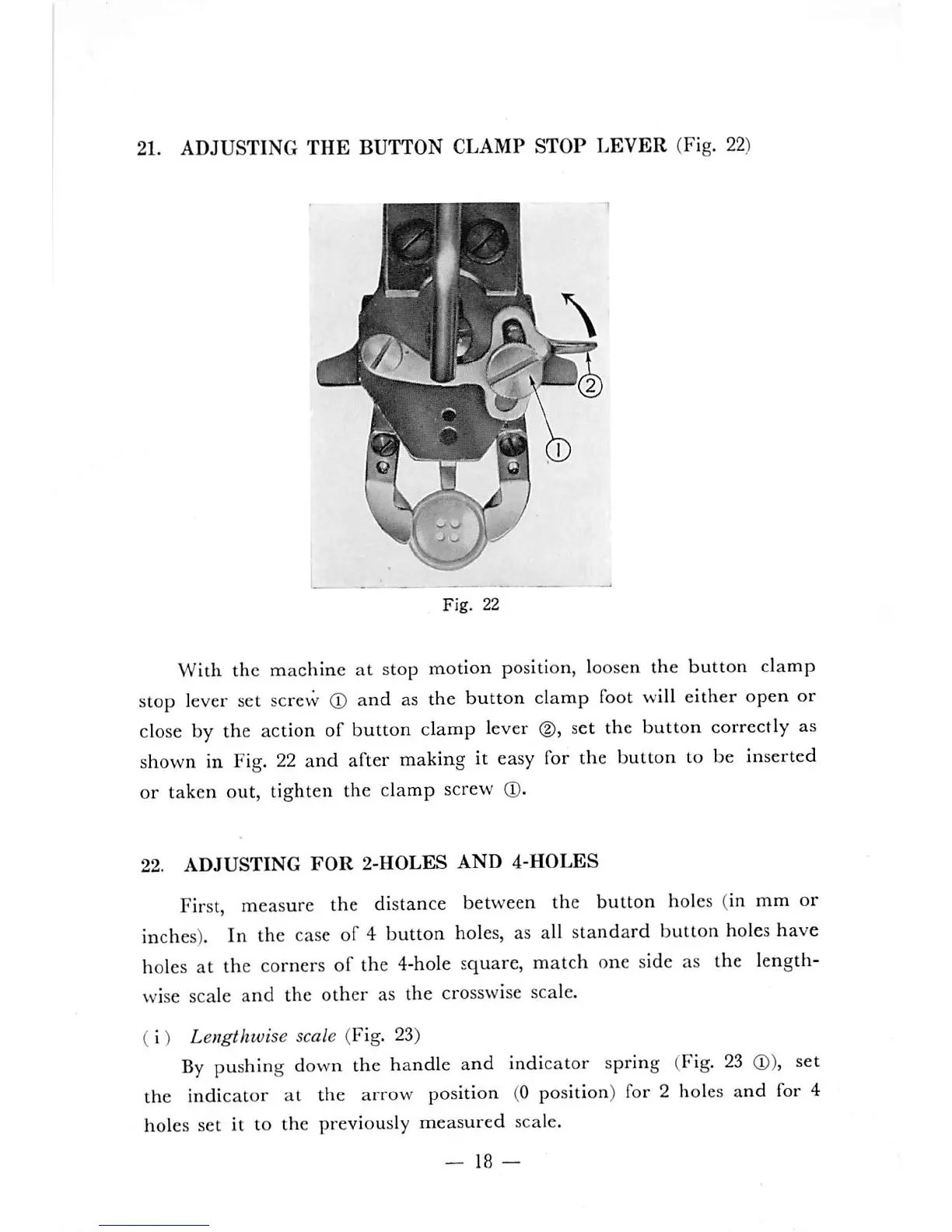
21.
ADJUSTING
THE
BUTTON
CLAMP
STOP
LEVER
(Fig. 22)
Fig.
22
With the machine at stop motion
position,
loosen
the button clamp
stop
lever
set
screw
(T)
and as the button
clamp
foot
will
either open or
close
by
the
action
of
button
clamp
lever
(2),
set
the
button
correctly
as
shown
in
Fig.
22
and
after
making
it
easy
for
the
button
to
be
inserted
or taken out, tighten the clamp screw
(1).
22.
ADJUSTING
FOR
2-HOLES
AND
4-HOLES
First,
measure
the distance
between
the button
holes
(in mm or
inches).
In the
case
of 4 button
holes,
as all standard button
holes
have
holes at the corners of the 4-hole square, match one side as the length
wise scale
and
the
other
as
the
crosswise scale.
(i)
Lengthwise scale (Fig. 23)
By
pushing
down
the
handle
and indicator
spring
(Fig.
23
(D),
set
the indicator at the arrow position (0 position) for 2 holes and for 4
holes set it to the previously measured scale.
—
18
—
 Loading...