KNX Room actuator 230 V
Ref.-no.: RA 23024 REGHE
4 Operation
4.1 Controls
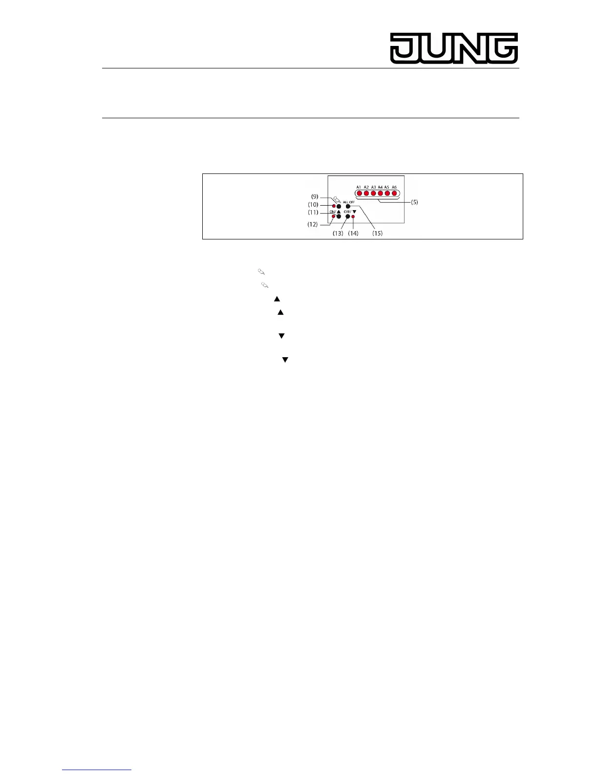
Fig.2: Controls – layout
(5) output status LEDs
(9) key : Manual control
(10) LED
: permanent manual control indicator
(11) key ON/ : switching on or opening a valve or raising a curtain / stop
(12) LED ON/ : lit up: switched on or blind/shutter moving upwards,
manual control mode
(13) key
OFF/ : switching off or closing a valve or lowering the
blind/shutter / stop
(14) LED
OFF/ : lit up: switched off or blind/shutter moving down,
manual control mode
(15) ALL OFF key: all outputs off, closing all valves and stopping all
drives
4.2 Status indication
The status LEDs A1...A6 (Fig. 2, 5) indicate the output states.
• Off: output is off
• On: output is on
• Flashing slowly: output in manual control mode
• Flashing fast: output disabled by permanent manual control mode
Heating outputs A5 and A6: The LED does not indicate the characteristics
of the valve drive, but the state of the output. ON = supplying current; OFF =
not supplying current.
In the PWM mode of operation, the LED indication cannot be interpreted as
representing the state of the valve drives connected and of the valves
controlled
4.3 Modes of operation
• Bus operation: operation via touch sensors or other bus devices
• Temporary manual control: manual operation locally with keypad,
automatic return to bus operation
• Permanent manual control mode: only manual operation locally on
device
L Bus operation in manual control mode disabled.
L Manual operation in the event of bus failure enabled.
L After failure and return of bus voltage, the device switches over to bus
operation.
4
 Loading...