20
Preparation
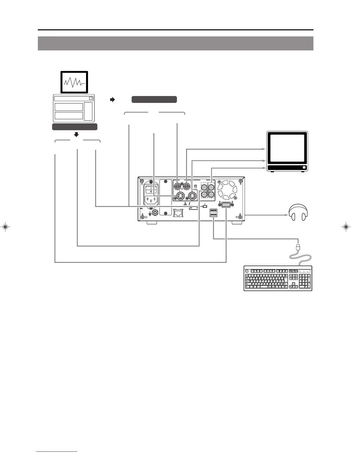
Signal Connections
䡵 Audio and video signals
Note 1: The video signal for input is selected using INPUT SELECT from the INPUT SELECT MENU screen.
Note 2: The audio signals for input are selected using INPUT SELECT from the INPUT SELECT MENU screen.
When either LINE or Y/C is set for INPUT SELECT, the analog audio signals from the AUDIO IN terminals will be selected
for input.
When DV is set for INPUT SELECT, the DV audio signals from the DV IN/OUT terminal will be selected for input.
Note 3: When the DVD recorder is in Stop or Recording mode, the video input signal is output on the E-E screen as a composite
video signal.
In addition, the Setup Menu and other setting screens are also displayed on the monitor connected to this terminal. The
DVD recorder’s operation status and other relevant information are displayed on-screen when DISPLAY from the DISPLAY
MENU screen has been set to ON.
Note 4: The Y/C IN/OUT terminal’s specification (i.e., S1 or S2) can be selected using Y/C TERMINAL MODE from the SYSTEM
MENU (2/2) screen. The same information as with the VIDEO LINE OUT terminal is output from the Y/C OUT terminal.
Note 5: The standard input level for audio signals input via the AUDIO IN terminals (i.e., +4 dB or –8 dB) can be selected using the
AUDIO INPUT LEVEL switch on the rear panel.
Note 6: Use the following cable as the DV cable.
VC-VDV204 (2m, 4P-4P) from JVC
VC-VDV206 (2m, 4P-6P) from JVC
Input
Input
Video output
DV IN/OUT
DV IN/OUT Y/C IN
Y/C OUT
PHONES
(on front panel)
LINE IN
LINE OUT
AUDIO OUT
AUDIO IN
RS-232C
REMOTE
DV
YC separate
YC separate
Analog audio
Analog audio
Composite
Composite
DV
USB
REMOTE
REMOTE cable
Headphones
Stereo
Keyboard
Monitor TV
VIDEO
POWER
MAIN
FOR SERVICE
FOOT SW
AUDIO
REMOTE
IN
IN
OUT
USB
1
2
+
4dB
-
8dB
OUT
DV IN/OUT
LINE
CH1
CH2
INPUT
LEVEL
Y/C
AC IN
Y/C
Audio output
Note 1
Note 3
Note 4
Note 4
Note 5
Note 6
Note 2
BD-X201MU/E(20_25).p65 05.1.14, 4:16 PM20
 Loading...