(No. 52152) 1-51
CONTRAST ADJUSTMENT (NTSC/PAL Y/C)
Measuring Instruments Signal generator (Crosshatch signal)
Oscilloscope
Card (Slot) NTSC/PAL Video Input Card (Slot 2)
Test Points TP-47G [CRT SOCKET PWB]
TP-GND [CRT SOCKET PWB]
Adjustment Points S*01 (Contrast) [Service Menu]
Notes:
• Ensure that the output waveforms from the NTSC/
PAL Video Input Cards are normal before proceeding
to the following adjustments.
• Perform the following adjustments after completing
the 1080/60i signal Contrast Adjustment.
• Set the CONTRAST data in the Setup Menu to “00”.
• The SO value (see the description of the HDTV
Contrast Adjustment) becomes the reference value
for the following adjustments. When this data is
changed, it is required to re-adjust the data of all of
the adjustment signals (HDTV, SDTV and NTSC/PAL).
When re-adjusting the 1080/60i signal, use the SI. (For
the adjustment of the 1080/60i signal, use the
Component/RGB Input Card.)
(1) Apply the NTSC crosshatch signal to INPUT D (Terminal
Y/C on the NTSC/PAL Video Input Card).
(2) Set the CONTRAST potentiometer on the front panel to
the center click position.
(3) Connect the oscilloscope across TP-47G and TP-GND.
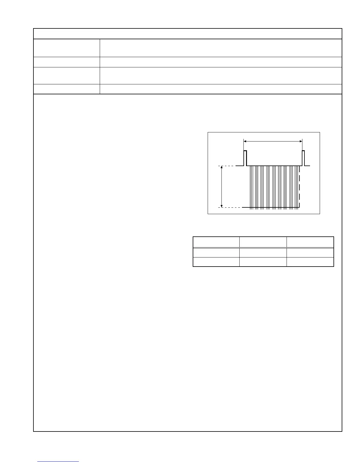
(4) Adjust SB01 in the Service Menu to set the voltage
amplitude <A> in the figure on the right to the voltage
shown in the Table 4.
(5) Vary the adjustment signal and adjustment data, and re-
perform adjustments in steps 1 to 4 above (see Table 4).
1 Vertical interval
(V. sync)
<A>
Adjustment Signal
Adjustment Data
Adjustment Voltage <A>
NTSC (Y/C) SB01 36 V ± 2 V
PAL (Y/C) SD01 36 V ± 2 V
Table 4
 Loading...