(No. 52152) 1-69
Adjustment Signal
White Balance HIGH White Balance LOW
Overscan Underscan Overscan Underscan
COMMON SR02 – SR06 –
1080/60i SI02 SP26 SI06 SP27
1080/50i SK02 SP32 SK06 SP33
1080/24psF SL02 SP35 SL06 SP36
720/60p SM02 SP38 SM06 SP39
720/50p SN02 SP41 SN06 SP42
BRIGHTNESS ADJUSTMENTS (HDTV)
Measuring Instruments Signal generator (Gray scale signal)
Card (Slot) Component/RGB Input Card (Slot 1)
Test Points
Adjustment Points S*02 (Overscan Bright High), S*06 (Overscan Bright Low),
SP** (Underscan Bright High/Low)
[Service Menu]
Notes:
• Perform the following adjustments after completing the Contrast and White Balance adjustments.
• Set the PICTURE SUB ADJ. data in the Setup Menu to “00”.
• The value adjusted at the SR adjustment becomes the reference value for the following adjustments. When this data
is changed, it is required to re-adjust the data of all of the adjustment signals (HDTV, SDTV and NTSC/PAL). When re-
adjusting the 1080/60i signal, use the SI.
• When overscan data of a signal is changed, it is required to re-adjust the underscan data of the same adjustment
signal.
• After completing the brightness adjustments, make sure that the Low-Light is not deviated. If it is, it is required to
perform the Low-Light adjustment again.
– Standard value (SO) adjustment –
<White Balance HIGH: D9300>
(1) Apply the 1080/60i component gray scale signal to INPUT A.
(2) Set “COLOR TEMP.” of COLOR TEMP./BAL. in the Setup Menu to HIGH.
(3) Set the PHASE, CHROMA, BRIGHT and CONTRAST potentiometers on the
front panel to the center click positions.
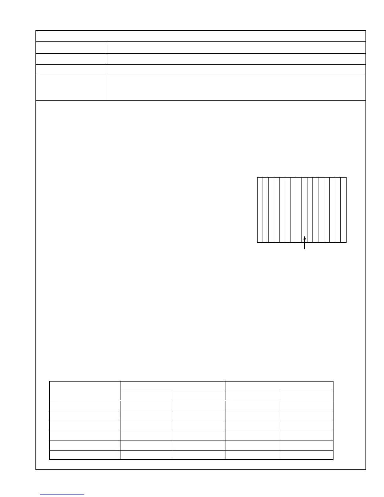
(4) Adjust SR02 in the Service Menu so that the 0% black area in the gray scale
signal lights up slightly. (Be sure to avoid degradation of the black color.)
<White Balance LOW: D65>
(5) Set “COLOR TEMP.” of COLOR TEMP./BAL. in the Setup Menu to LOW.
(6) Adjust SR06 so that the 0% black area in the gray scale signal lights slightly.
(Be sure to avoid degradation of the black color.)
– Other signals adjustments –
<White Balance HIGH: D9300>
(7) Apply the 1080/60i component gray scale signal to INPUT A.
(8) Set “COLOR TEMP.” of COLOR TEMP./BAL. in the Setup Menu to HIGH.
(9) Set the PHASE, CHROMA, BRIGHT and CONTRAST potentiometers on the front panel to the center click positions.
(10)Adjust SI02 in the Service Menu so that the 0% black area in the gray scale signal lights up slightly.
(Be sure to avoid degradation of the black color.)
(11) Set the UNDER SCAN button on the front panel to ON so that the scanning size is underscanning.
(12)Adjust SP26 so that the 0% black area in the gray scale signal lights slightly. (Be sure to avoid degradation of the black color.)
(13)Set the UNDER SCAN button on the front panel to OFF.
<White Balance LOW: D65>
(14)Set “COLOR TEMP.” of COLOR TEMP./BAL. in the Setup Menu to LOW.
(15)Adjust SI06 so that the 0% black area in the gray scale signal lights slightly. (Be sure to avoid degradation of the black color.)
(16)Set the UNDER SCAN button on the front panel to ON so that the scanning size is underscanning.
(17)Adjust SP27 so that the 0% black area in the gray scale signal lights slightly. (Be sure to avoid degradation of the black color.)
(18)Set the UNDER SCAN button on the front panel to OFF.
(19)Vary the adjustment signal and adjustment data, and re-perform adjustments in steps 7 to 18 above (see Table 21).
4.10.12 BRIGHTNESS ADJUSTMENTS
Table 21
0% Black area
0
%
2 4 6 8 10 12 14 0
%
2 4 6 8 10 12 14
%
 Loading...