1-66 (No. 52152)
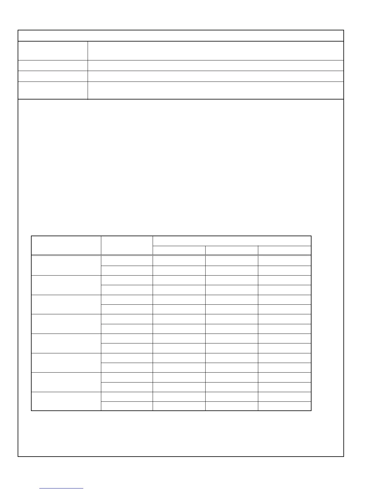
Adjustment Signal Function
Adjustment Data
RG B
COMMON
Drive WW01 – WW03
Cut off WW04 WW05 WW06
1080/60i
Drive WI01 – WI03
Cut off WI04 WI05 WI06
1080/50i
Drive WM01 – WM03
Cut off WM04 WM05 WM06
1080/24psF
Drive WO01 – WO03
Cut off WO04 WO05 WO06
720/60p
Drive WQ01 – WQ03
Cut off WQ04 WQ05 WQ06
720/50p
Drive WS01 – WS03
Cut off WS04 WS05 WS06
480/60i
Drive WE01 – WE03
(Common to 576/50i)
Cut off WE04 WE05 WE06
480/60p
Drive WG01 – WG03
(Common to 576/50p)
Cut off WG04 WG05 WG06
COMPONENT SIGNAL WHITE BALANCE (HIGH: D9300) ADJUSTMENTS
Measuring Instruments Signal generator (10-step gray scale signal)
Color temperature meter
Card (Slot) Component/RGB Input Card (Slot 1)
Test Points
Adjustment Points W*01 (Drive (R)), W*03 (Drive (B)), W*04 (Cut Off (R)),
W*05 (Cut Off (G)), W*06 (Cut Off (B)) [Service Menu]
Notes:
• Perform the following adjustments after completing the Low-Light White Balance (Reference Value) Adjustment.
• Set the COLOR TEMP./BAL. data in the Setup Menu to “00”.
• The values adjusted with WW become the reference values for the following adjustment. When this data is changed,
it is required to re-adjust the white balance data of all of the adjustment signals (Component, NTSC and PAL).
When re-adjusting the 1080/60i signal, use the WI.
(1) Apply the 1080/60i component 10-step gray scale signal to INPUT A.
(2) Set “COLOR TEMP.” of COLOR TEMP./BAL. in the Setup Menu to HIGH.
(3) Set the PHASE, CHROMA, BRIGHT and CONTRAST potentiometers on the front panel to the center click positions.
(4) Adjust WW01 and WW03 in the Service Menu using the color temperature meter so that the color temperature is set as shown
below.
(Do not touch WW02.)
Color temperature : HIGH (D9300). x = 0.283, y = 0.297 (Reference value)
(5) Ensure that the white balance tracking is correct from the gray scale steps with lower color temperatures to those with higher
color temperatures. If the white balance tracking is deviated in darker steps, adjust WW04 to WW06 to correct it.
(Do not set the values of WW04 to WW06 no more than “50”.)
(6) Vary the adjustment signal and adjustment data, and re-perform adjustments in steps 1 to 5 above (see Table 18).
Table 18
 Loading...