1-48 (No. 52152)
CONTRAST ADJUSTMENT (HDTV)
Notes:
• Perform the following adjustments after completing
the Screen Voltage Coarse adjustment.
• Set the CONTRAST data in the Setup Menu to “00”.
• The value adjusted at the SR adjustment becomes
the reference value for the following adjustments.
When this data is changed, it is required to re-adjust
the data of all of the adjustment signals (HDTV, SDTV
and NTSC/PAL). When re-adjusting the 1080/60i
signal, use the SI.
– Standard value (SR) adjustment –
(1) Apply the 1080/60i crosshatch signal to INPUT A (Terminal
Y on the Component/RGB Input Card).
(2) Set the CONTRAST potentiometer on the front panel to
the center click position.
(3) Connect the oscilloscope across TP-47G and TP-GND.
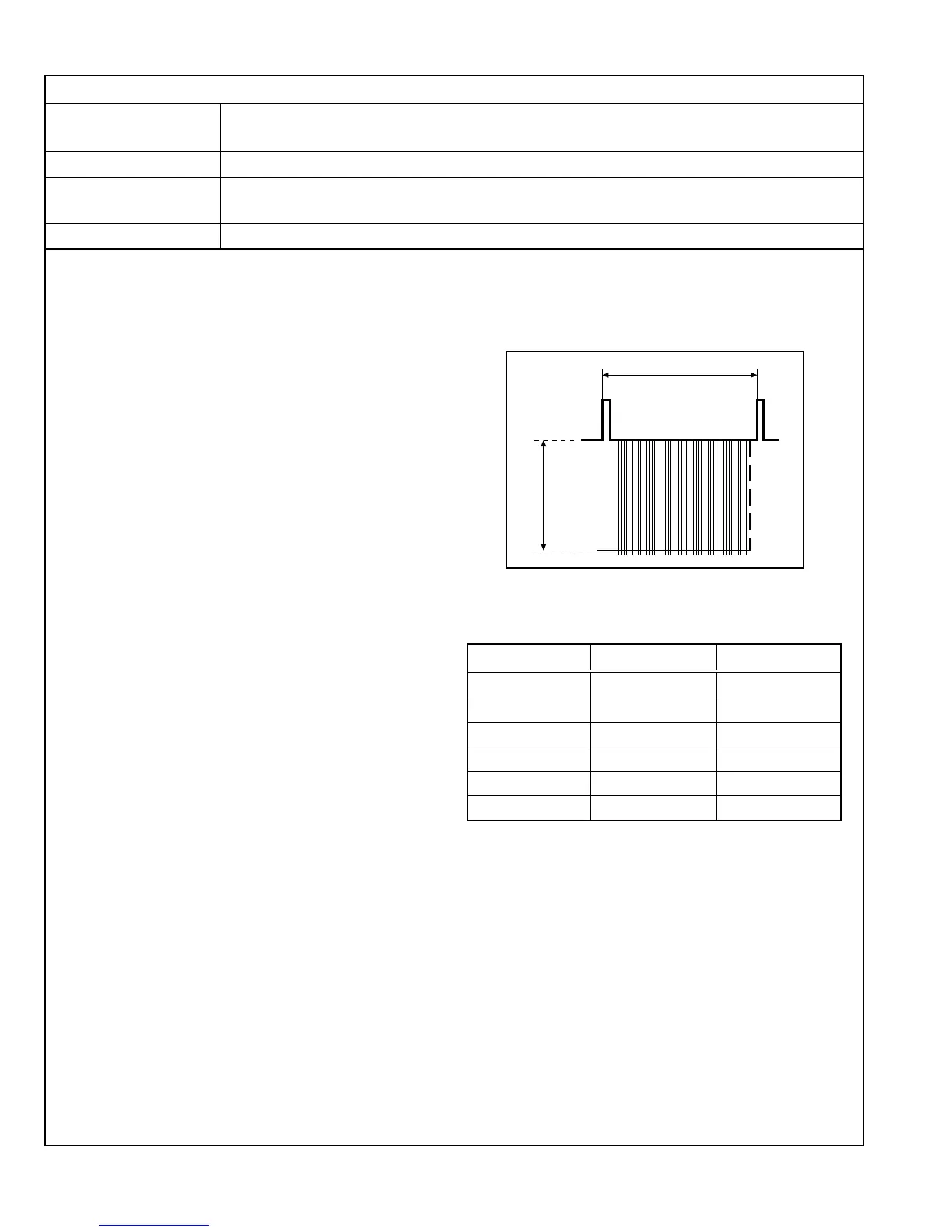
(4) Adjust SR01 in the Service Menu to set the voltage
amplitude <A> in the figure on the right to the voltage
shown in the Table 1.
– Other signals adjustments –
(5) Apply the 1080/60i crosshatch signal to INPUT A (Terminal
Y on the Component/RGB Input Card).
(6) Set the CONTRAST potentiometer on the front panel to
the center click position.
(7) Connect the oscilloscope across TP-47G and TP-GND.
(8) Adjust SI01 in the Service Menu to set the voltage
amplitude <A> in the figure on the right to the voltage
shown in the Table 1.
(9) Vary the adjustment signal and adjustment data, and
re-perform adjustments in steps 5 to 8 above (see Table
1).
4.10.8 CONTRAST ADJUSTMENTS
1 Vertical interval
(V. sync)
<A>
Adjustment Signal
Adjustment Data
Adjustment Voltage <A>
COMMON(1080/60i)
SR1 30 V ± 2 V
1080/60i SI01 30 V ± 2 V
1080/50i SK01 32 V ± 2 V
1080/24spF SL01 33 V ± 2 V
720/60p SM01 32 V ± 2 V
720/50p SN01 32 V ± 2 V
Table 1
Measuring Instruments Signal generator (Crosshatch signal)
Oscilloscope
Card (Slot) Component/RGB Input Card (Slot 1)
Test Points TP-47G [CRT SOCKET PWB]
TP-GND [CRT SOCKET PWB]
Adjustment Points S*01 (Contrast) [Service Menu]
 Loading...