(No. 52152) 1-59
VERTICAL IMAGE POSITION, IMAGE AMPLITUDE AND IMAGE DISTORTION ADJUSTMENTS (SDTV OVERSCAN 16:9 MODE)
Measuring Instruments Signal generator (Size adjustment signal, Crosshatch signal)
Card (Slot) Component/RGB Input Card (Slot 1)
Test Points
Adjustment Points DY** (Vertical Size), DY** (Vertical Position), DY** (Side Pin Distortion), CE** (Corner Distortion
(W)), CE** (Corner Distortion (S)), CE** (Parallelogram Distortion), CE** (Trapezoidal Distortion),
CE** (Horizontal Arc Distortion) [Service Menu]
(1) Apply the 480/60i size adjustment signal to INPUT A
(Terminal Y on the Component/RGB Input Card).
(2) Press the ASPECT button on the front panel to set the
scanning size to 16:9 mode.
(3) Set the CONTRAST and BRIGHT potentiometers on the
front panel to the center click positions.
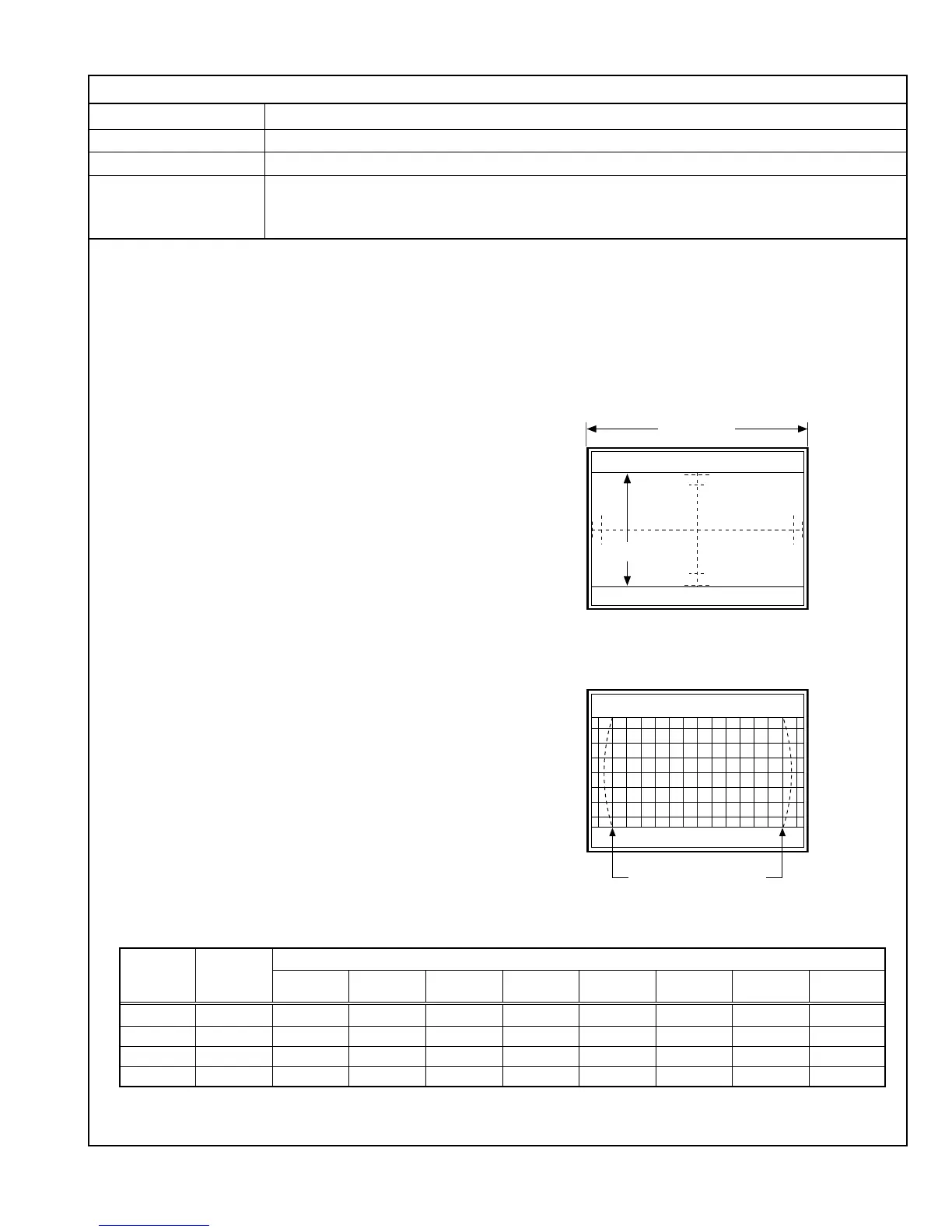
(4) Adjust DY14 in the Service Menu to set the vertical position
of the image at the center of the CRT screen.
(5) Adjust DY13 to set the vertical amplitude of the image to
193mm.
(6) Apply the 480/60i crosshatch signal to INPUT A.
(7) Adjust CE08 to optimize the trapezoidal distortion (observe
the second vertical lines from the left and right edges as the
reference).
(8) Adjust CE07 to optimize the parallelogram distortion (observe
the second vertical lines from the left and right edges as the
reference).
(9) Adjust CE09 to optimize the horizontal arc distortion.
(10)Adjust DY15 so that the second vertical lines from the left
and right edges are linear.
(11) If there is an extreme corner S-shape distortion, adjust CE06
to optimize it (this adjustment is usually unnecessary).
(12)If there is an extreme corner W-shape distortion, adjust CE05
to optimize it (this adjustment is usually unnecessary).
(13)Apply the 480/60i size adjustment signal to INPUT A.
(14)Ensure that the vertical amplitude of the image is 193mm. If
it is not, adjust DY13 again.
(15)Adjust DY14 so that the vertical position of the image comes
at the center of the CRT screen.
(16)Vary the adjustment signal and adjustment data, and re-
perform adjustments in steps 1 to 15 above (see Table 12).
193mm
Make these lines linear.
Screen size
Adjustment Adjustment
Adjustment Data
Step No. Signal
Vertical Vertical Side Pin Corner Corner
Parallelogram
Trapezoidal Horizontal
Position size Distortion
Distortion (W) Distortion (S)
Distortion Distortion
Arc Distortion
1 480/60i DY14 DY13 DY15 CE05 CE06 CE07 CE08 CE09
2 480/60p DY26 DY25 DY27 CE15 CE16 CE17 CE18 CE19
3 576/50i DY20 DY19 DY21 CE10 CE11 CE12 CE13 CE14
4 576/50p DY32 DY31 DY33 CE20 CE21 CE22 CE23 CE24
Table 12
Notes:
• Perform the following adjustments after completing the Reference Mode (SDTV overscan 4:3 mode) adjustments.
• The corner distortions (W) & (S), parallelogram distortion, trapezoidal distortion and horizontal arc distortion adjustment
data for this adjustment are common to those in the SDTV overscan 16:9 mode and the SDTV underscan 16:9 mode
adjustments. This adjustment data needs to be adjusted in either mode.
• The corner distortions (W) & (S), parallelogram distortion, trapezoidal distortion and horizontal arc distortion adjustment
data for this adjustment are common to those in the 480/60i and NTSC signal or 576/50i and PAL signal adjustments.
This adjustment data needs to be adjusted with either signal.