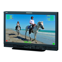
(No. 52152) 1-73
• SIGNAL PWB ASS'Y
IC801
• MAIN PWB ASS'Y
IC510
• MOTHER PWB ASS'Y
IC103
• REMOTE PWB ASS'Y
IC102, IC103
• SIGNAL PWB ASS'Y
IC104, IC601, IC801
•
FRONT CONTROL PWB ASS'Y
IC101
• SIGNAL PWB ASS'Y
IC801, IC805
•
SUB DEF MODULE PWB ASS'Y
IC001
• SIGNAL PWB ASS'Y
IC801
•
HV CONTROL MODULE PWB ASS'Y
IC503
• SIGNAL PWB ASS'Y
IC801
• MAIN PWB ASS'Y
• SIGNAL PWB ASS'Y
IC801
•
SUB DEF MODULE PWB ASS'Y
IC005
5.1 SELF DIAGNOSIS
The unit incorporates a self-diagnosis function and is capable of indicating the absence of raster by blinking on the front panel LEDs
and the on-screen display.
5.1.1 DISPLAYING THE SELF DIAGNOSIS INDICATIONS
(1) LED indication: When raster is absent, the six LEDs of INPUT SELECT A to F on the front panel blink to indicate this condition.
(2) On-screen display: The self diagnosis results can be displayed when the unit is on.
5.1.2 LED INDICATION
(1) Operation during an LED indication:
The main microcomputer detects any abnormalities in communication on the I
2
C and causes the LEDs to blink.
At the same time, the unit is turned off to protect it but the LEDs keep on blinking.
At this time, the main microcomputer does not accept commands except for the POWER switch on the front panel.
(2) How to cancel the LED blinking:
Press the POWER switch on the front panel to turn the unit ON again.
(3) Types of LED indications
LED INDICATION TYPE
ON-SCREEN DISPLAY
DIAGNOSIS RESULT MALFUNCTIONING CIRCUIT
I
2
C-0
DEFLECTION BUS
I
2
C-1 SIGNAL BUS
I
2
C ROM BUS
X-RAY
OCP
VOFF
INPUT A blinking
at 0.5-second
intervals
INPUT B blinking
at 0.5-second
intervals
INPUT C blinking
at 0.5-second
intervals
INPUT D blinking
at 0.5-second
intervals
INPUT E blinking
at 0.5-second
intervals
INPUT F blinking
at 0.5-second
intervals
Communication error in the signal buses
(SCL0, SDA0) of I
2
C
Communication error in the signal buses
(SCL1, SDA1) of I
2
C
Communication error in the ROM buses
(SCL2, SDA2) of I
2
C
X-rays detected
Overcurrent detected
Neck-break prevention detected
SECTION 5
TROUBLE SHOOTING
 Loading...