(No. 52152) 1-61
HORIZONTAL/VERTICAL IMAGE POSITION, IMAGE AMPLITUDE AND IMAGE DISTORTION ADJUSTMENTS (NTSC/PAL OVERSCAN 4:3 MODE)
Measuring Instruments Signal generator (Mono-scope signal, Crosshatch signal)
Card (Slot) NTSC/PAL Video Input Card (Slot 2)
Test Points
Adjustment Points D*01 (Horizontal Size), D*02 (Vertical Size), D*03 (Horizontal Position), D*04 (Vertical Position),
D*05 (Side Pin Distortion), D*06 (Corner Distortion (W)), D*07 (Corner Distortion (S)), D*08
(Parallelogram Distortion), D*09 (Trapezoidal Distortion), D*10 (Horizontal Arc Distortion), D*11
(Vertical Linearity (S Correction)), D*12 (Vertical Linearity (C Correction)) [Service Menu]
(1) Apply the NTSC mono-scope signal to INPUT C (Terminal
VIDEO1 on the NTSC/PAL Video Input Card).
(2) Set the CONTRAST and BRIGHT potentiometers on the
front panel to the center click positions.
(3) Adjust DA04 in the Service Menu to set the vertical position
of the image at the center of the CRT screen.
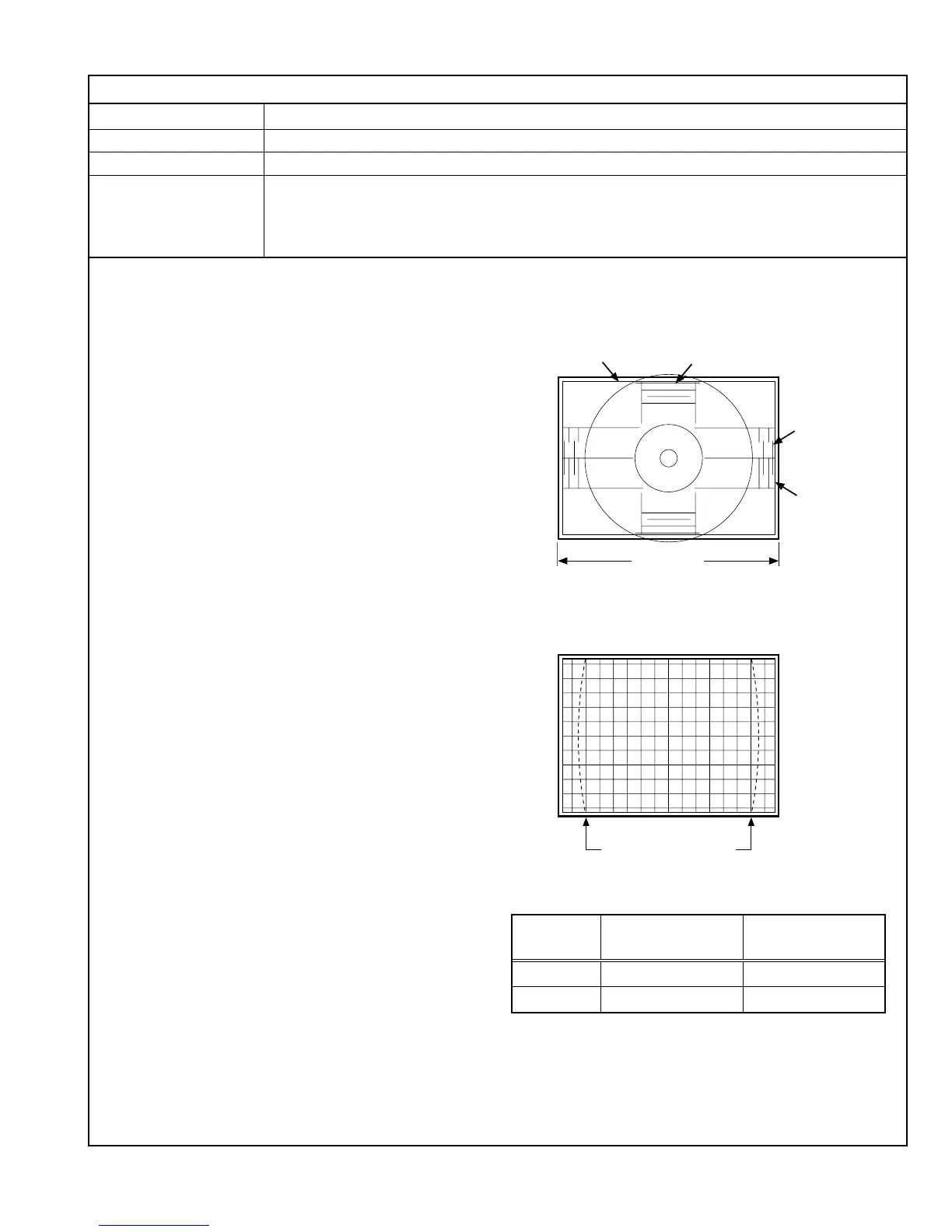
(4) Adjust the vertical image amplitude with DA02 to match the
95% line of the mono-scope signal onto the edge of the
escutcheon.
(5) Apply the NTSC crosshatch signal to INPUT C.
(6) Adjust DA11 to set the sizes of the rectangles at the center
of the image and those at the left and right ends to be
identical.
(7) Adjust DA12 to set the sizes of the rectangles at the center
of the image and those at the top and bottom to be identical.
(8) Ensure that the center position is not deviated. If it is, adjust
DA04 again.
(9) Adjust DA11, DA12 and DA04 repeatedly until the center
position and vertical linearity are optimized.
(10)Adjust DA09 to optimize the trapezoidal distortion (observe
the second vertical lines from the left and right edges as the
reference).
(11) Adjust DA08 to optimize the parallelogram distortion
(observe the second vertical lines from the left and right
edges as the reference).
(12)Adjust DA10 to optimize the horizontal arc distortion.
(13)Adjust DA05 so that the second vertical lines from the left
and right edges are linear.
(14)If there is an extreme corner S-shape distortion, adjust DA07
to optimize it (this adjustment is usually unnecessary).
(15)If there is an extreme corner W-shape distortion, adjust DA06
to optimize it (this adjustment is usually unnecessary).
(16)Apply the NTSC mono-scope signal to INPUT C.
(17)Observe the vertical amplitude of the image. If it is dislocated,
adjust DA02 again.
(18)Adjust DA03 so that the horizontal position of the image
comes at the center of the CRT screen.
(19)Adjust the horizontal image amplitude with DA01 to match
the 95% line of the mono-scope signal onto the edge of the
escutcheon.
(20)Vary the adjustment signal and adjustment data, and re-
perform adjustments in steps 1 to 19 above (see Table 14).
90
90
90 80
80
80
Make these lines linear.
Escutcheon
Escutcheon 95% line
95% line
Screen size
Adjustment Adjustment Adjustment
Step No. signal Data
1 NTSC DA
2PAL DC
Table 14
 Loading...