1-10
1.4 DISASSEMBLY/ASSEMBLY OF CAMERA SECTION
AND DECK SECTION
1.4.1 Flowchart of disassembly
The following flowchart shows the disassembly of the cam-
era section and deck section. When assembly of the cam-
era section and deck section, follow this flowchart in the re-
verse order.
<Camera section/Deck section>
For details of disassembly
manner, refer to page 1-12,
“1.5 REPLACEMENT OF
CCD IMAGE SENSOR.”
4 Frame assembly
5 Cassette housing assembly
1
Zoom unit assembly
2 Main board assembly
3 OP block assembly
(Incl. CCD board assembly)
3 OP block assembly
3
CCD board assembly
7
7
7
7
7
7
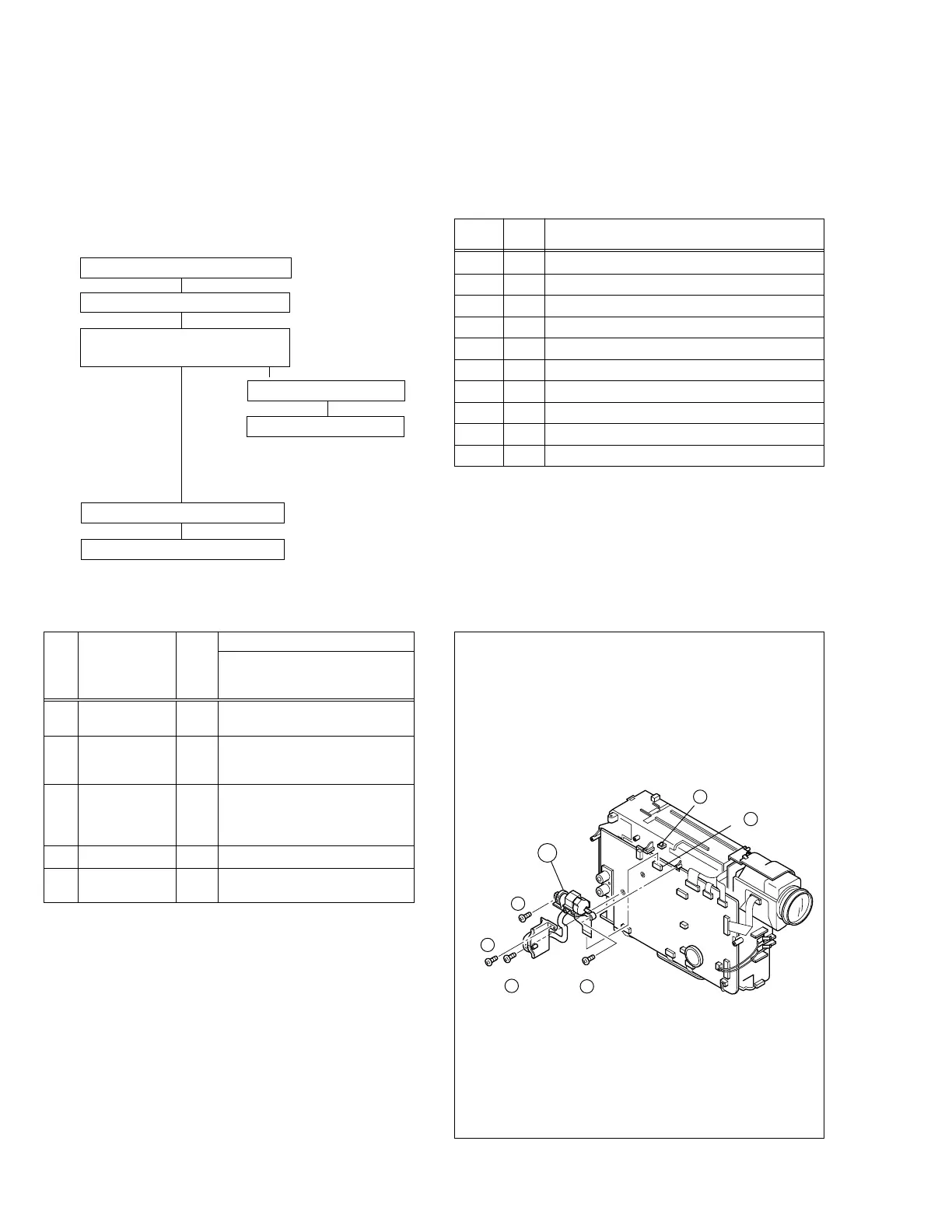
1.4.2 Disassembly method
1
ZOOM UNIT D1 4(S1),(L1a),*CN1a
ASSEMBLY
2
MAIN BOARD D2 2(S2),(L2a)
*CN2a,*CN2b,*CN2c,CN2d,
CN2e,*CN2f,*CN2g,*CN2h,*CN2j
3
OP BLOCK D3 2(S3),CUSHON (OP)
ASSEMBLY
(Incl. CCD BOARD
ASSEMBLY)
4
FRAME ASSEMBLY D4 2(S4a),2(S4b),(S4c)
5
CASSETTE HOUSING
D5 4(S5)
ASSEMBLY
STEP
/LOC
No.
PART
Fig.
No.
REMOVAL
*UNLOCK/RELEASE/
UNPLUG/UNCLAMP/
UNSOLDER
List of Abbreviations:
2(S1)=2 screws (S1)
4(L1a)=4 Locking Tabs (L1a)
CN=Connector
Reference Notes:
<NOTE 1>
Destination of connectors
Note :
Two kinds of double-arrows in connection tables
respectively show kinds of connector/wires.
⇔ : Flat wire
←→ : Wire
Con-
nector
Connector
CN
1
a 14 MAIN CN13 ⇔ ZOOM UNIT
CN
2
a 14 MAIN CN2 ⇔ SENSOR
CN
2
b 11 MAIN CN5 ⇔ VIDEO/FLY. E HEAD
CN
2
c 10 MAIN CN1 ⇔ DRUM MOTOR
CN
2
d 2 MAIN CN4 ←→ LOADING MOTOR
CN
2
e 2 MAIN CN6 ←→ DC LIGHT
CN
2
f 22 MAIN CN15 ⇔ OP BLOCK
CN
2
g 14 MAIN CN22 ⇔ CCD
CN
2
h 11 MAIN CN7 ⇔ A/C HEAD
CN
2
i 18 MAIN CN3 ⇔ CAPSTAN MOTOR
No.of
Pins
Fig. D1
(L a)
1
CN a
1
(S )
1
1
(S )
1
2
(S )
1
3
(S )
1
4
1
 Loading...