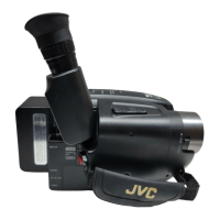
3-2
3.2 ELECTRONIC VIEWFINDER (E. VF) ADJUSTMENT
Notes:
•
Unless otherwise specified, all measurement points and
adjustment parts are located on E. VF board.
•
After adjustment or replacement of the deflection yoke
or the centering magnet, fix it by the band as shown the
figure below.
Fig. 3-2-1 E. VF
•
After adjustment is completed, compare the picture on
the E. VF screen with the monitor TV.
CENTERING
MAGNET
CRT
TOP VIEW
STOPPER
Fig. 3-2-2 E. VF
CENTERING
MAGNET
CRT
F.B.T
STOPPER
3.2.1 Tilt
Subject • Alignment tape
• Stairstep
Mode • PB
Equipment • E. VF
Measurement point • E. VF screen
Adjusting part • Deflection yoke
Specification • The picture is visible as same as
monitor TV.
Fig. 3-2-3 E. VF board
VR7001
V. SIZE
VR7002
BRIGHT
60 E. VF PWB ASSY
CN7001
T7001
CN7002
VR7003
FOCUS
1) Put the deflection yoke to the most inner side of CRT
neck first. Then fix the stopper temporary.
2) Adjust the tilt of picture on the E. VF screen by tilting
the deflection yoke.
3) Fix the stopper completely.
3.2.2 Centering
Subject • Alignment tape
• Stairstep
Mode • PB
Equipment • E. VF
Measurement point • E. VF screen
Adjusting part • Centering magnet (CRT assy)
Specification • The center of the E. VF screen
1) While observing the viewfinder screen, adjust the
centering magnet to locate the stairstep in the center
of the view-finder screen.
3.2.3 Vertical scanning
Subject • Camera picture
Mode • EE
Equipment • E. VF
Measurement point • E. VF screen
Adjusting part • VR7001 (V. SIZE)
Specification • Normal picture amplitude
1) Observing the viewfinder screen, adjust VR7001 for nor-
mal picture amplitude.
3.2.4 Brightness
Subject • –
Mode • EE
• Lens closed
Equipment • E. VF
Measurement point • E. VF screen
Adjusting part • VR7002 (BRIGHT)
Specification •
The CRT raster is just barely visible
1) Close the lens with the cap and adjust VR7002 so that
the raster of the CRT is just visible in the E. VF.
3.2.5 Focus
Subject • Camera picture
Mode • EE
Equipment • E. VF
Measurement point • E. VF screen
Adjusting part • VR7003 (FOCUS)
Specification •
The center area is clear and defined
1) While observing the viewfinder screen, adjust VR7003
so that the picture at the central area of the screen is
clear and defined.
 Loading...