1-12
1.5 REPLACEMENT OF CCD IMAGE SENSOR
Notes:
•
Pay the most careful attention to the transparent glass and
optical LPF of the CCD image sensor so a not the soil and
damage them. If something is soiled with finger-prints, etc.,
gently clean it with silicon-processed paper/cloth or cham-
ois.
•
When the CCD image sensor is shipped from the factory,
there are protection seals applied onto the transparent
glass. Leave the protector as it is, and take it off just be-
fore assembling the CCD image sensor to the OP block.
1.5.1 Removal of CCD image sensor
1. Remove two screws (1, 2) securing the CCD base assy,
and disassemble the CCD spacer, the optical LPF,
spacer rubber.
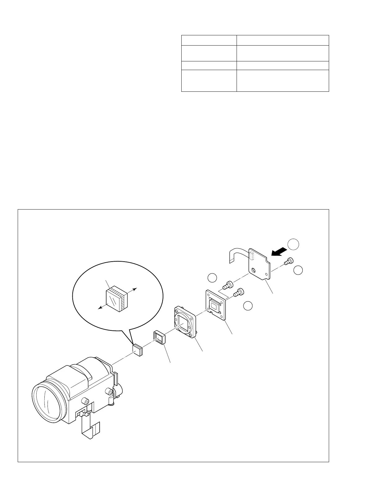
1.5.2 Installation of new CCD image sensor
1. Remove the protection seal from a new CCD image sen-
sor. Next, put the optical LPF, spacer rubber, CCD
spacer on the CCD image sensor as they are piled up
in this order. At that time, make sure of orientation of each
item refering to the following table (see Fig. 1-5-1).
Part Name Orientation
CCD image sensor Mark is on the right viewed as indi-
cated by the arrow a .
Spacer rubber IC side is horizontal.
Optical LPF Marks are on the left and bottom
viewed as indicated by the arrow
a .
2. Fix the CCD base assy to OP block with the two screws
(1, 2) . At that time, be careful of the orientation.
3. After completion of all P.C. boards to the camera sec-
tion, observe the monitor to confirm no vignetting caused
by the bodytube, rings, lens hood, etc. If no vignetting
is observed, it can be said that image's parallel,
horizontality and centering are correct.
1.5.3 Replacement of CCD board assy
1. Remove one screw (3).
2. Unsolder at the fourteen points on the CCD board assy.
Note:
1. Remove the screw (3) only when the CCD board
assy needs replacement.
2.
When installing a new CCD board assy, carry out
the above-mentioned procedure in the reverse order.
Fig. 1-5-1
OPTICAL LPF
SPACER RUBBER
CCD SPACER
CCD BASE ASSEMBLY
a
OP
SIDE
CCD
SIDE
BLUE
CCD BOARD
ASSEMBLY
(S a)
1
1
(S a)
2
1
(S b)
3
1
∗
: 0.147 N
•
m (1.5 kgf
•
cm)
∗
 Loading...