1-9
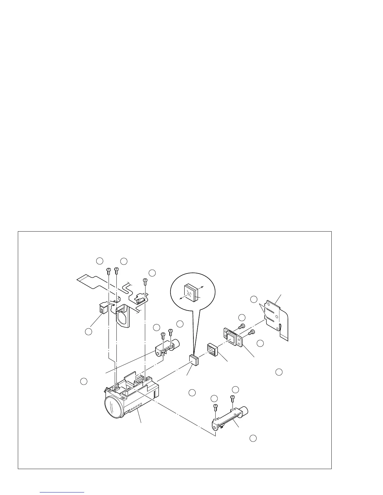
Fig. 1-5-1
1.5 DISASSEMBLY OF @ OP BLOCK ASSEMBLY/CCD
BOARD ASSEMBLY
1.5.1 Precautions
1. Carefully handle the CCD image sensor, optical LPF,
lens, etc. during the disassembly work. Pay the most
careful attention to the surface of those parts not to get
it soiled, scratched or dusty. If some of those surfaces
gets soiled with fingerprints, etc., wipe it out with silicone
paper, clean chamois, cleaning cloth or the like.
2. The new CCD image sensor is occasionally shipped from
the factory as a protection seal is applied onto its trans-
parent glass. If so, leave the protection seal as it is and
remove it just before installing the CCD image sensor in
the OP block assembly.
1.5.2 How to remove @ OP block assembly and CCD
board assembly
1. Unsolder at the fourteen points (SD@) and remove the
CCD board assembly.
2. Remove the two screws (1, 2) and then remove the CCD
base assembly.
Note
@
a:
Carefully remove the CCD base assembly, be-
cause the space rubber and optical LPF may be
removed together with the CCD image sensor.
Note
@
b:
When replacing the CCD image sensor, don’t re-
place it individually but replace the CCD base as-
sembly in whole with a new one.
1.5.3 How to install @ OP block assembly and CCD
board assembly
1. Install the optical LPF with the @ OP block assembly.
2. With the spacer rubber left attached to the CCD base
assembly, install the assembly in the OP block assem-
bly and clamp it using the two screws (1, 2).
3. Set the CCD board assembly in the CCD base assem-
bly, and fasten it by soldering at the fourteen points
(SD@).
1.5.4 Replacement of service parts
Service parts to be supplied for the OP block assembly are
as follows.
When replacing a part, be very careful not to get the FPC
wire broken or damaged by soldering (overheating).
1. Focus motor
2. Zoom motor
3. Iris motor unit
Note
@
c:
When soldering the FPC wire of the focus motor
or zoom motor during the replacement work, be
sure to keep the tip of a soldering iron approxi-
mately 1 mm above the terminal.
Note
@
d:
The iris motor unit includes one FPC assembly
and two sensors.
(S a)
1
12
NOTE a,b
12
NOTE c
12
CCD
<05>
(S b)
3
12
(S b)
4
12
(S c)
5
12
(S c)
8
12
(S c)
9
12
(S c)
6
12
(S c)
7
12
(S a)
2
12
CCD BASE
ASSY
SPACER
RUBBER
NOTE a
12
NOTE d
12
OPTICAL
LPF
IRIS MOTOR
UNIT
OP BLOCK
FOCUS MOTOR
NOTE c
12
ZOOM MOTOR
OP
SIDE
CCD
SIDE
BLUE
∗
∗
∗
∗
∗
∗
∗
∗
12
∗
∗
: 0.118 N
•
m (1.2 kgf
•
cm)
(SD )
 Loading...