1-3
1
COVER (UNDER) Fig.1-3-1 (S1) —
2
COVER (SHOE) Fig.1-3-2 2(S2), 2(L2) —
3
MIC COVER ASSY
(S3a), 2(S3b) —
4
UPPER CASE ASSY
Fig.1-3-3a (SD CARD) NOTE4a
(Inc.MONITOR ASSY)
NOTE4b
Fig.1-3-3b
(S4a), (S4b), 3(S4c), 2(S4d),
NOTE4c
2(S4e), (S4f),
NOTE4d
CN 4a, CN4b
5
MONITOR ASSY Fig.1-3-4 2(S5a), GUIDE(MONI), 2(S5b) NOTE5
6
SHUTTER ASSY Fig.1-3-5
(S
6
)
NOTE
6
7
BOTTOM ASSY Fig.1-3-6
CN
7
, 2(S
7
a), 2(S
7
b), 3(S
7
c),
NOTE7
(S7d)
8
LOWER CASE ASSY
Fig.1-3-7 CN8a, CN8b, NOTE8
(Inc. MICROPHONE,
SHEET(SHUTTER),
E.VF UNIT, CN8c, CN8d, CN8e, 3(S8)
OP MDA BOARD
ASSY,SHOE ASSY,
OP BLOCK ASSY)
9
MAIN BOARD ASSY
Fig.1-3-8 SHEET(SHUTTER), 2(S9) —
(L9a), SHIELD ASSY, CN 9a,
CN 9b, CN 9c, CN 9d,
(L9b), CN 9e, CN 9f
0
MECHANISM ASSY
(S0a),BRACKET(PRE/REC),
3(S
0
b),BRACKET(MECHA) ASSY
!
MICROPHONE Fig.1-3-9a — NOTE!
@ OP BLOCK ASSY (S@), 2(S$a) NOET@
#
E.VF UNIT
(S#a), (S#b), CN# NOTE
#
a
NOTE#b
NOTE#c
$
OP MDA BOARD Fig.1-3-9b 2(S$b), CN@ NOTE$
a
ASSY NOTE$
b
%
SHOE ASSY
CN%
, 2(S%)
NOTE
%
STEP
No.
PART
Fig.No.
POINT NOTE
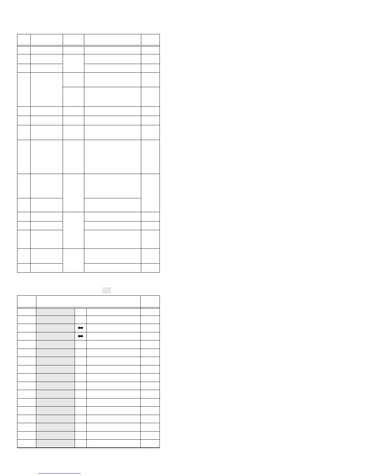
1.3.2 Disassembly method
Table 1-3-2
NOTE
4
a:
If a card is installed, remove it in advance.
NOTE
4
b:
Be careful not to damage the battery removal switch.
When disassembling, ensure that the lock lever is in the
low position and set the battery removal switch only to
the up position.
NOTE
4
c:
A screw (14) is located inside the Cover (MULTI/USB).
NOTE
4
d:
Slide down the shutter and remove the screw (15).
NOTE
5
:
Refer to Fig. 1-4-1 for the disassembly method.
NOTE
6
:
Be careful not to damage or lose the parts.
NOTE
7
:
Take care of the removed screws.
NOTE
8
:
For the disassembly/assembly of the E. VF unit, Shoe
assembly, OP MDA board assembly, and OP block as-
sembly, see section 1.8, “SERVICE KNOW-HOW”.
NOTE
!
:
Leave the microphone connected to the OP block as-
sembly.
NOTE
@
:
Refer to Fig. 1-5-1 for the disassembly method.
NOTE
#
a:
Be careful not to cut the FPC wire or damage any of
the switches during work.
NOTE
#
b:
Refer to Fig. 1-6-1 for the disassembly method.
NOTE
$
a:
Be careful not to lose the parts.
NOTE
@
,
#
c,
$
b,
%
:
When assembling, attach the OP block assembly, E.VF
assembly and the shoe assembly on the OP MDA board
assembly and install them together in the lower case
assembly.
CONN.
No.
Pin No.
CONNECTOR
Note:
Remove the parts marked in .
CN
4
a MAIN CN112 ⇔ SUB OPE UNIT - 8
CN
4
b MAIN CN113 ⇔ MONITOR CN401 39/33
CN
7
MAIN CN107 BOTTOM CN301 50
CN
8
a MAIN CN110 OP MDA CN201 80
CN
8
b MAIN CN111 ⇔ CCD - 20
CN
8
c MAIN CN109 ⇔ ZOOM OPE UNIT - 13
CN
8
d MAIN CN108 ↔ EJECT SW - 2
CN
8
e MAIN CN115 ↔ MICROPHONE - 4
CN
9
a MAIN CN102 ⇔ LOADING MOTOR - 6
CN
9
b MAIN CN103 ⇔ ROTARY ENCODER - 6
CN
9
c MAIN CN101 ⇔ HEAD - 8
CN
9
d MAIN CN106 ⇔ SENSOR - 16
CN
9
e MAIN CN105 ⇔ CAPSTAN MOTOR - 18
CN
9
f MAIN CN104 ⇔ DRUM MOTOR - 11
CN@ OP MDA CN204 ⇔ OP BLOCK ASSY - 24
CN# OP MDA CN203 ⇔ VF BL CN7001 20
CN% OP MDA CN202 ⇔ SHOE ASSY - 16/13
Table 1-3-3
 Loading...