2-19
Fig. 2-8-1
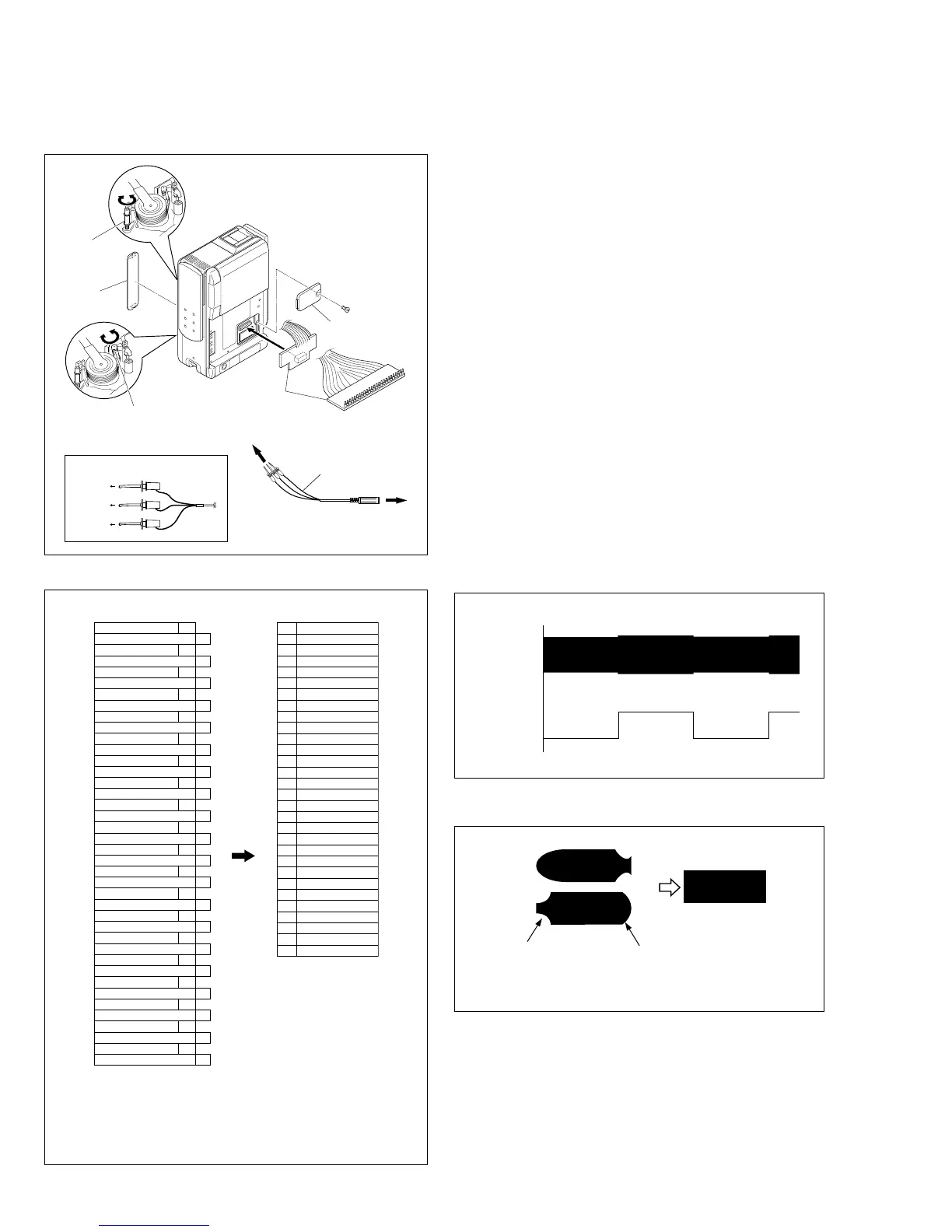
2.8 COMPATIBILITY ADJUSTMENT
2.8.1 Jig connector cable connection
Remove one screw (1) first and the cover (JIG) next.
COVER
(JIG)
COVER
(M.ADJ)
GUIDE ROLLER
(SUP) ASSY
GUIDE ROLLER
(TU) ASSY
JIG CONNECTOR
CABLE
1
RED
to 6 pin
( JLIP_RX )
WHITE
BLACK
to 25 pin
( JLIP_TX )
to 15 pin
( GND )
JIG CONNECTOR COMMUNICATION CABLE
COMMUNICATION
CABLE
TO PC
CABLE
TO JIG CONNECTOR CABLE
2.8.2 Tape pattern check
(1) Play back the compatibility adjustment tape.
(2) While triggering the MAIN CN114-11PIN (HID1), ob-
serve the waveform of CN114-29PIN (ENV_OUT).
(3) Confirm that the waveform is free from remarkable
level-down, and entirely parallel and straight.
Moreover, perform the following adjustment as re-
quired.
(4) In case any level-down is observed on the left hand
side, straighten the level by turning the guide roller of
the pole base assembly (supply).
In case any level-down is observed on the right hand
side, however, straighten the level by turning the guide
roller of the pole base assembly (Take-up).
(5) After adjustment, try the unloading motion once, and
confirm that the waveform is flat (straight) when the
tape has been played back again.
Moreover, perform readjustment as required.
(6) When the recording has been played back again, play
back the self-recording to confirm that the waveform
is flat.
Fig. 2-8-3
Fig. 2-8-4
CN114-29
(ENV_OUT)
CN114-11
(HID1)
Flatten the waveform.
Misalignment of guide roller
height on the take-up side
Misalignment of guide
roller height on the
supply side
Note:
When an adjustment is performed with the lower case cover
attached, first slide the Cover (M.ADJ) open and then per-
form the compatibility adjustment.
Be sure not to damage the cover plate when sliding it open
to make an adjustment because it must be re-positioned af-
ter completing the adjustment.
NOTE)
The JIG connector board uses 30 of the 40 pins of
CN114 on the Main board.
Pins 1 to 5, 21 to 24 and 34 of CN114 on the Main board
are not used.
MAIN
CN114
VF_RPD 40
CVF_G 20
CVF_R 39
CVF_B 19
VF_COM 38
MT_RPD 18
MT_G 37
MT_R 17
MT_B 36
MT_COMCS 16
MT_PSIG 35
GND 15
GND 34
MONI_CHG 14
SBE 33
SPA 13
FRP 32
FS_PLL 12
DISCRI 31
HID1 11
ATFI 30
MAIN_VCO 10
ENV_OUT 29
PB_CLK 9
TRST 28
TCMK 8
TMS 27
TDO 7
TDI 26
JLIP_RX 6
JLIP_TX 25
IF_TX 5
AL_3VSYS 24
CJIG_RST 4
VPPC 23
SRV_RX 3
SRV_TX 22
REG_3V 2
DRST 21
VPPD 1
JIG CONN. BOARD
(PIN NO.)
40 VF_RPD
39 CVF_R
38 VF_COM
37 MT_G
36 MT_B
35 MT_PSIG
33 SBE
32 FRP
31 DISCRI
30 ATFI
29 ENV_OUT
28 TRST
27 TMS
26 TDI
25 JLIP_TX
20 CVF_G
19 CVF_B
18 MT_RPD
17 MT_R
16 MT_COMCS
15 GND
14 MONI_CHG
13 SPA
12 FS_PLL
11 HID1
10 MAIN_VCO
9 PB_CLK
8 TCMK
7 TDO
6 JLIP_RX
Fig. 2-8-2
 Loading...