1-12
1.8 SERVICE KNOW-HOW
When performing disassembly/assembly work to this model,
the parts that are most complicated and require special at-
tention are the E. VF unit and the OP MDA board, OP block
and shoe assemblies, all of which are mounted inside the
lower case assembly.
Care should be taken in handling these parts as they are
mounted inside the lower case assembly (except the E.VF
unit) and there is a lack of adequate space to work conven-
iently. This section gives further details regarding the disas-
sembly procedures, although they have been described in
previous sections.
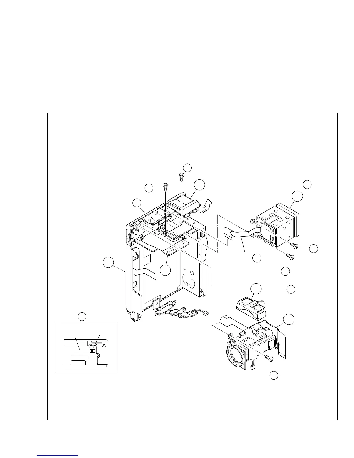
1. See Fig. 1-8-1.
(1) While moving the ! microphone out of way, remove the
screw (39) and take out the @ OP block assembly.
(2) Remove two screws (40, 41) and open the $ OP MDA
board assembly.
(3) Remove two screws (42, 43) to disconnect the connec-
tor (CN203), then take out the FPC to remove the # E.
VF unit.
Note #a :
Be careful not to damage the FPC or the switches
when carrying out this work.
Fig. 1-8-1
11
8
12
15
13
NOTE
11
NOTE
OP MDA
PWB
a
13
NOTE a
13
NOTE b
13
CN
13
(S b)
43
13
(S a)
42
13
14
SW
(S a)
40
14
(S a)
41
14
(S )
39
12
 Loading...