1-34 (No.MB263)
4.2 Arrangement of adjusting positions
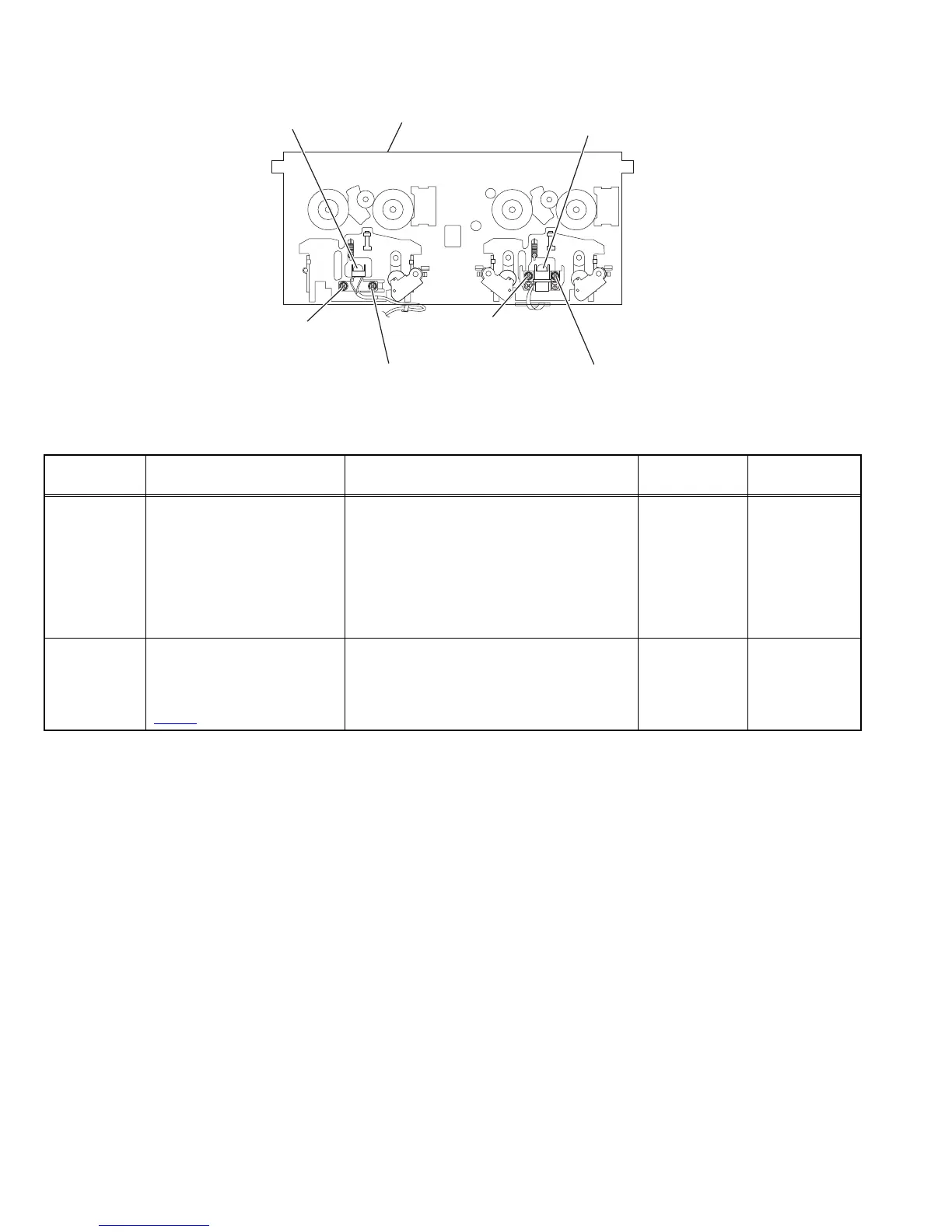
4.2.1 Tape recorder section
Cassette mechanism assembly
(Front side)
PB Head
(Deck-A)
REC/PB Head
(Deck-B)
Head azimuth screw
(Forward side)
(Reverse side)
(Forward side)
Head azimuth screw
Head azimuth screw
Head azimuth screw
(Reverse side)
Item
Measurement
conditions
Measurement method Ref. value
Adjustment
position
Cassette Head
Azimuth Align-
ments
Test tape
:VT703 (10kHz)
Measurement output terminal
:Left and Right speaker output
(6Ω loaded)
or
Headphone Output
(32Ω loaded)
(1) Playback the test tape VT703 (10KHz) or
equivalent.
(2) Adjust the head azimuth screw to obtain
maximum output and both output of L / R
is in 3dB.
(3) Put on the screw lock paint after align-
ments.
Maximum output Adjust the head
azimuth screw
only when the
head has been
changed.
Recording Bias
Frequency
Alignment
Test tape
:TYPE I AC-514
Measurement output terminal
:Erase head terminal
(CN308
8-Pin)
(1) Insert the recording tape in deck-B.
(2) Starting the recording.
(3) Adjust the oscillation frequency to
80kHz+/-3kHz by core of Oscillation coil
of L301.
80kHz+/-3kHz Use the High Im-
pedance Probe
or Frequency
counter input.
 Loading...